We often see many car drivers, to forgot to turn off lights in a car when parking. Then, they back to start the machine, it did not work. Because a battery does not has a energy.
Do you want it to happen to you? This Headlight Warning buzzer circuit can help you. Some called headlight reminder circuit. It will alert you! If…
- Switch it off the start SW
- Close the car door But turn on headlights in the car
Ways 1: Headlight Warning buzzer circuit
In the circuit, Two transistors Q1 and Q2 are an astable multivibrator circuit. The collector of the Q2 connects to a loudspeaker to be a load of the circuit.
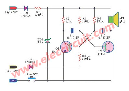
Headlight Warning buzzer circuit diagram
You may also like these:
The capacitors C1, C2, and resistors R3, R4 are timing section and to set a frequency of output signal.
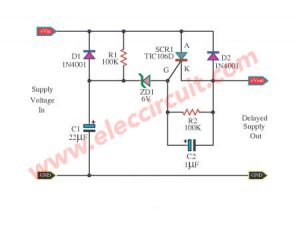
First of all, we turn on the light switch. Then, the electric currents come to diode-D1 and a resistor-R1. It is the positive voltage power supply of this circuit. Next, some currents flow to the ZD1-9.1V Zener diode. It keeps the voltage across ZD1 to provide a constant 9 volts.
The ground wire connects to the door switch to the cabin light. Which is controlled by the door. This switch will connect to the ground, just when the door open only.
Suppose that we turn off the start switch and turn on headlights up. Then the driver opens the door. The Oscillator generator circuit will work.
The buzzer produces a loud tone at a frequency of about 1500 Hertz. It will alert us forgot to turn off the light in the car.
What is more?
Are you forgot to turn off car lights?
Look at below Even greater.
Ways 2: Headlight reminder circuit
Are you forgot to turn off car lights?
If we forget to turn off the lights in the car or headlights on all night but in the morning you could not even start the car Because batteries lose some voltage, we lets to build the warning forgot off lights circuit better.
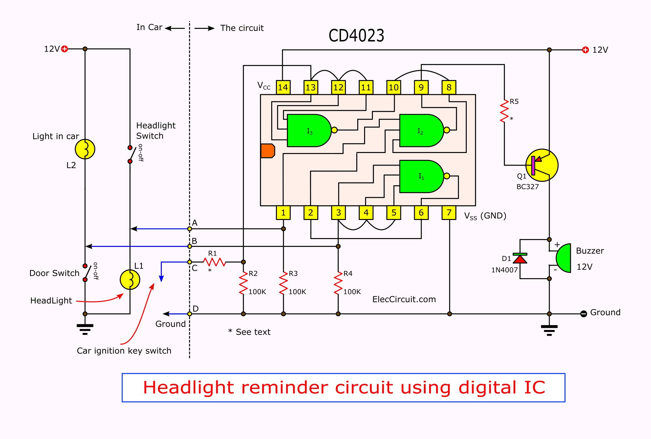
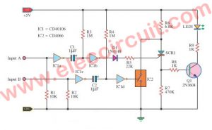
As perfect circuit in Figure 1. Use CMOS-IC no-MC14023B. Which is a NAND gate 3 input, Quantity: 3, a small transistor and a Buzzer only.
When rotate the car ignition key switch to stop the engine. If turns off the small headlights and opening the door out of the car, warning buzzer will sound immediately.
The working principle.
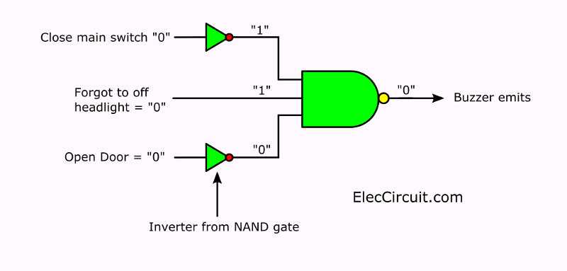
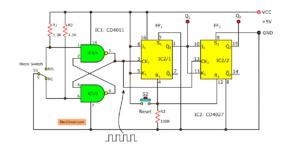
The working of headlight alarm circuit in Figure 2. This circuit use all NAND gate, We see the conditions that the buzzer has three reasons.
1. Rotate the Car ignition key switch to stop the engine. If engine not works also no voltage to charges the car battery. The voltage at switch should of 0-volts or state is “0”.
2. Forgot turns off the small headlight show that headlight still current and voltage at it should has about of 12-volts or state is “1”.
3. Opening the door to get out the car. The voltage may be 12 volts or 0 volts as each brand cars. Suppose the voltage is “0”, or state “0” and conditions third item is the input signal to our circuit.
Then we see the 3 NAND gate input that we use. This gate is NAND, so if input is all “1” state, will be output equals “0” and it is the only case to the output is “0”.
If others input will has output is “1” all the times.
Use this features we will use this conditions cause the buzzer loud.
In when we need “1” so we need to reverse the logical state “0” to “1” by inverter. Which in this case we use others NAND into inverter form to saving IC.
See in Figure 2. We will use NAND gate- I2 inside MC14023B is are a decision making logic circuit. For I1 and I3 will be use as inverter gate to reverse the logical state of an incoming signal.
In Figure 1 from terminal A, which will wiring to headlight switch. If forgot turns off switch will has voltage is 12 volts. Therefore, is signal “1”. This signal will be connected to pin 1. Which is directly input of I2-NAND gate. The terminal B, which is connected to the door switch, the signal this terminal is “0”, if the door is opened and the lamp in car is brightness, this signal will be connected to through the I1-NAND gate, to reverse signal from “0” into “1”, Then so entered in the input of I2 next.
In addition,the door switch of some brands may be connected with a 12 volts or state “1”. We need to modify our circuit by connect this signal to input of I2 as Figure 2. Therefore, your car in which form, should check it before assemble this project.
For the the car ignition key switch will connect to the terminal C, this signal will has voltage is 0 volts. If stop engine. When is signal “0” so connect through I3 to reverse signal into “1” then in to I2 again.
The output of I2, which is pin 8 that is As a result, the decision conditions to be used to the buzzer loud. If we want to buzzer loud when output is “0”, so use how to connecting through resistor to drive the 2SC561- PNP-transistor.
When signal is “0” will has current flow from the power supply through emitter – base ,resistor in to the gate. This current will be amplify as collector current to drive buzzer.
If output is “1” or voltage is 12 volts. Which equals the power supply voltage also will noting have current flow in this section the buzzer so not loud.
In circuit has connecting as accessories for example: Resistor, Diode , R1 are connected to protects a high voltage which may be the start switch.
The R2-R4 are resistors that connects to protect when Input is left alone Because the switch Prevent electrostatic influence by reduce resistance input of CMOS down to same the resistors only.
The 1N4001-diode is connected to protect a noise signal while running which Which may be interrupting the operation of the circuit.
The case of Figure 1, there is NAND I1, which is not in use. Usually the gate is not in use, do not leave it and let the input. because the CMOS has very high input resistance. May be static or interference Itti’s easy. Should be connected to ground or the power supply.
The circuit assembly.
For ICs, transistor, and diode will use others that has any features comparable, Resistors size ¼ watts Precision, 5, 10 or 20%. The buzzer is small size at 12 volts and current less than 100 mA.
Soldering the wires on PCB should be tight. If this handset equipped with a vibration in the car all the time. Wires may be detached easily. Should be soldered IC on PCB directly over the IC socket.
Creating a project It is not difficult But is installed on the car is the more difficult, which would be a function of your friends, if you want to do this project.
The component list
IC1: MC14023B or TC4023 or CD4023
Q1: BC327 45V 800mA PNP Transistor
D1: 1N4007, 1000V 1A Diodes
R1,R5: 22K = 2 pcs.
R2-R4: 100K = 3 pcs
Buzzer 12V
The perforated board
Terminal, wires, and others.
GET UPDATE VIA EMAIL
I always try to make Electronics Learning Easy.
I love electronic circuit. I will collect a lot circuit electronic for teach my son and are useful for everyone.
In my 20210 Nissan370 roadster the forgot headlight buzzer is shared with the open top as well. How can I cancel this buzzer in the cabin? My top is not working and can’t spend $8000. to replace the hydraulic system.
Any suggestions
Hello, luis Mora,
Sorry, but I have not worked with that type of car. Therefore, I cannot give you any meaningful suggestions. It is not best for me to suggest something outside of my expertise.
Best,
Apichet