We use the DIY infrared remote extender circuit to control the satellite receiver from any room in the house.With a single receiver.Save money not having to buy additional equipment.
Now the satellite receiver are steadily increased popularity. If you are one of those. And you want to Watch the favorites and control it. From every room in the house. By using a satellite dish only one set. This problem is solved by using this increase the range of applications of remote control circuit.
How it works
Principle of increasing range applications of the remote control is It will receives the signals from the infrared remote control. Then converted into electrical signals sent to the infrared LED stick on a lead The receiver.This way we can use the remote control receiver. The distances of up to 20-30 feet ever.
Note:
There are many remote circuit, other circuit that I recommend are:
Small RF universal remote controls

How This Circuit works
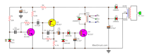
The complete circuit is shown in Figure 1. The transistor Q1 is the infrared photo-transistor will convert the infrared signal form the remote control into a square pulse. Then pass a capacitor C1 and resistor R3 to IC1 to amplify the signal up.
If no resistor R1, Transistor Q1 will conduct current the excess until saturated.
Since the infrared signal from the remote control weak. So we use LED1 sensitivity, installed on the back of Q1,that it sends infrared light to Q1, makes Q1 conduct current a little. Even do not have infrared light from the remote control.
Signal through capacitor C1 will be extended up to 1,000 times by IC1. The gain set by resistors R3 and R4. Then through the Zener diode ZD1 which is the sliding voltage levels circuit. The ZD1 will not applied current until the pulse output from IC1 will has voltage higher than the Zener voltage.
Which cut the signal noise at low voltage level. The signal that via ZD1 will be extended an additional 10 times. The gain of IC2 is determined by both resistor R5 and R6 before send to IC3/1(LM339) and IC3/2 next.
IC1 and IC2 use number LM741 that is a signal op-amp. Because the inverting pin of IC1 is connected with a reference voltage, but the non-inverting pin of IC2 is connected to ground. Connecting like this circuit, if using dual op-amp IC type or four op-amp in one, it will cause the mutual interference. Because this type of ICs uses bias network circuit and the same set power supply. Using a single IC. Separately to make less noise, more stability and sensitivity up.
IC3/1 is set as the compare circuit by there is VR2 fine reference output voltage of IC3/2 connect with Q2 by through R10. That Q2 will drive LED2 as an infrared LED. In applications will attach the LED2 at the remote control input point of the satellite receiver.
For IC3/2 works like IC3/1, but LED3 a plain LED. It is pointed that a signal is being received. The blinking frequency, while the received light infrared.
Recommended: How does a SCR thyristor work?
How to builds
We assembled equipments as shown in Figure 2.

The parts list
Resistors size 1/4W 5%
R1: 15K
R2, R3, R13: 1K
R4: 1M
R5, R7, R9, R11: 10K
R6: 100K
R8: 150 ohm
R10, R12: 4.7K
VR1, VR2: Trimpot 20T
Polyester Capacitor 63V
C1: 0.01uF
C2: 0.1uF
Semiconductor devices
LED1, LED2: Infrared LED NO. TIL38
LED3: LED Red
Q1: Photo transistor No.TIL414
Q2: 2N2222, 45V 800mA NPN Transistor
ZD1: 5.1V 400mW
IC1, IC2: LM741 Single Operational Amplifier
IC3: LM339, Low Power Low Offset Voltage Quad Comparator
AC adaptor 9V 500 mA,
Customization
When I check the device that nothing wrong, then applies power into this circui. If LED3 lit up to adjust VR2 until LED3 go out. After then apply the voltmeter measure at pin 3 of IC1, adjust VR1 until can be read 4.55 volt. Release the meter wire then adjust VR2 until LED3 lit up. And then adjust VR2 fall back slightly until LED3 go out. As customization is completed to maximum sensitivity.
This project can be used with all kinds of electronics. Using infrared remote control.
GET UPDATE VIA EMAIL
I always try to make Electronics Learning Easy.
Related Posts
I love electronic circuit. I will collect a lot circuit electronic for teach my son and are useful for everyone.
Hi, this is a very interesting circuit, and i’d like to know if you have a better image of figure 2, it’s a very low res and barely see the components layout against the printed circuit board.
Regards