You stay cool on a hot summer day with a fan. Is it good? It can alarm turn on with itself when hot.
This is automatic fan controller circuit project. When the sensor system gets hot, this will control speed motor of the fan so highest. It uses a few components and easy to buy at local markets. And so easy to build on small size PCB. Also, you can modify it to more controls anything as you need with contact of the relay.
It uses an LM334z as a temperature sensor that is accurate. A cooling system in electronic working is very needed for small electronic projects. In addition to will need to use the heatsink, also must use a fan to blow at the heatsink. And when the projects use too much power, so too heat. We need to increase the speed of the fan. Which it requires high energy and lot of noise.
This project will control the fan to works when the heatsink is very hot only. The fan is not running all the time, Thus saving energy and No annoying fan noise. The same way Laptop computers.
We can bring this project to adopt wide variety applications. and high efficiency, detect temperature precisely.
How this project works
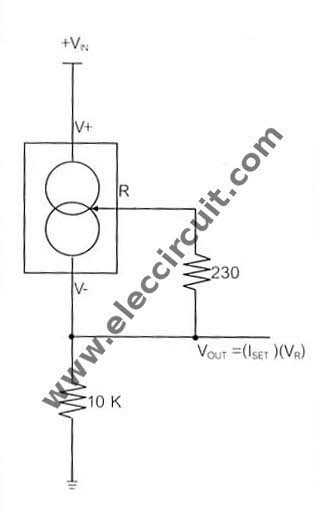
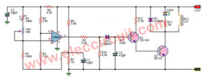
Figure 1 Real temperature sensor circuit.
LM334z is the constant current source and temperature sensor, can detect temperature that 0-70 degrees Celsius. Error less than 2 degrees. Easy to use and cheap. Because shaped like a transistor 2N3904, which we are familiar as well.
LM334 is IC that is used as constant current source and temperature sensor. By there are all four models shaped. Which can notice at a character end of IC number.
We now suggest only LM334Z. Which has chassis features as TO92 by Figure 1. Since it is cheap and easy to use. So, widely used in general project. The temperature that IC can be detected in the 0 to 70 degrees Celsius. So the error under 2 degrees. But if the temperature is more or less than this. May have a higher error.

Characteristics chassis in a TO92 of LM334z.
From base circuit of LM334Z-IC number. Which will causes it works on characteristics as the constant current source that output is “lset”, can be found below.
Iset = {(Vr)/Rset} x (1.059)____Equation 1.
When, Iset = Total current out of the IC.
VR = The voltage across combined Rset.
Rset = Fixed resistor.
(1.059) = The ratio between Iset and Ivias. (As constant the specification of the IC.)
From such features causes voltage output from IC has characteristics is linear as well. The value of voltage that drop across the Rset will changes according to temperature, as shown in figure 3
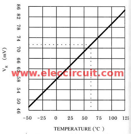
When the temperatures rise then the voltage cross the Rset will also high up. Which the values obtained??, can be instead of in Equation 1, to calculate the next time.
Features
1mA to 10mA Operation
0.02%/V Regulation
0.8V to 40V Operating Voltage
Can be Used as Linear Temperature Sensor
Draws No Reverse Current
Supplied in Standard Transistor Packages
Applications
Current Mode Temperature Sensing
Constant Current Source for Shunt References
Cold Junction Compensation Constant-Gain Bias for Bipolar Differential Stage
Micropower Bias Networks
Buffer for Photoconductive Cell
Current Limiter
This projects we use an LM334z as the base of a circuit for the temperature sensor. First, we need to calculate the Vout is out of the LM334Z. then need to define the desired temperature to circuit works. Suppose, we want the circuit operates at 60 degrees Celsius. And then bring the VR Instead in the formula. By set the circuit as Figure 1 the result Iset.
Iset = (71mA /230) x (1.059)
= 326.91 uA.
Find the Vout = (326.91uA)(10K)
= 3.27 volts
From the calculation, Vout is equal to 3.27 volts at 60 degrees. (Vout = 2.92V at 25 degrees) next, Let’s see the principle of the circuit
Beginning of the voltage comparators are IC1 / 1 and IC1 / 2, From connecting circuit as Figure 2, into pin 6 of IC1/2 can get voltage from adjusting VR1 that be determined at 3.27V as calculated.

Automatic fan controller circuit diagram.
The pin 3 of IC1/1 will be obtained the voltage from pin 6 of IC1/2, in pin 5 and will get Vout-voltage, to compare voltage causes each pin 1 and pin 7 no voltage
The period 3rd, pin 1 no voltage, pin 7 has voltage due to causes each 3 case, because LM334Z has to change at Vout there are:
– In normal conditions, first case But when the temperature rising up to the lowest that setting will cause the second ranges, higher temperature itself.
When you reach the point we set, by adjusting the VR1 resulted in the period 3rd. In the end, from all the three cases. We can cut-off a fan work, by adding the IC2. Which this IC2 will be the R-S- flip-flop IC. When cause first case, the voltage at pin 1 will to reset IC2 cause no voltage bias to Q1. The Q1-transistor so not work.
And then into 2 cases will not change, but then into period second also not change, next, but into period 3rd at pin 7 of IC1/2 will have voltage and pin 1 of IC1/1 will not has voltage.
The voltage from pin 7 will go to set IC2, send voltage to bias Q1 Q1 so work and also cause the relay pull in power to the fan. It so works well.
But when the temperature lower down than the period 3rd come to period second, the IC2 will also sen voltage to bias the Q1, because not reset the IC2.
When that the period second to first, IC2 will stop send voltage to bias Q1, cause the fan stop working.
Read next: What is SCR and how it works
How to assemble circuits

Consists of 2 section are the temperature sensor section and the main circuit (Figure 3). 1. the sensor unit and R1, R2- resistors will be assembled on Universal PCB Board as well, then connect the wire to the main circuit.
Should starting with small component before or low such as diode, resistors then in order of height, for the IC should put a socket.
Automatic fan controller circuit PCB layout
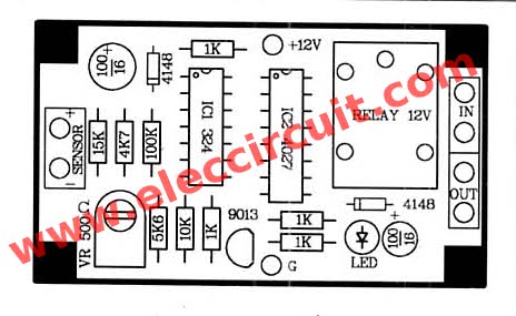
The Components layout of this projects.
Applications of this Automatic fan controller project
The testing this project
When the project is completed. Next to connect the 12V DC regulator power supply only because making circuit working incorrectly. Then adjust VR1 as calculated. By measure voltage at pin 6 of IC1, then adjust until a value as you want and test measure at pin 3 of IC1, the voltage will differ of 0.2V.
When adjusting completely, then put LM334Z near a heat generator such as Soldering iron etc. Do not touch directly, may cause the IC damage. then measure the voltage at pin 5 or pin 2 of IC1 will find that voltage increased, and more. When to point we setting VR1, the relay will work LED1 will glow.
and then we pull the Soldering iron go out, the voltage will lower down, later the temperature low down as that we set, the relay will stop and LED1 also go out.
The applications.
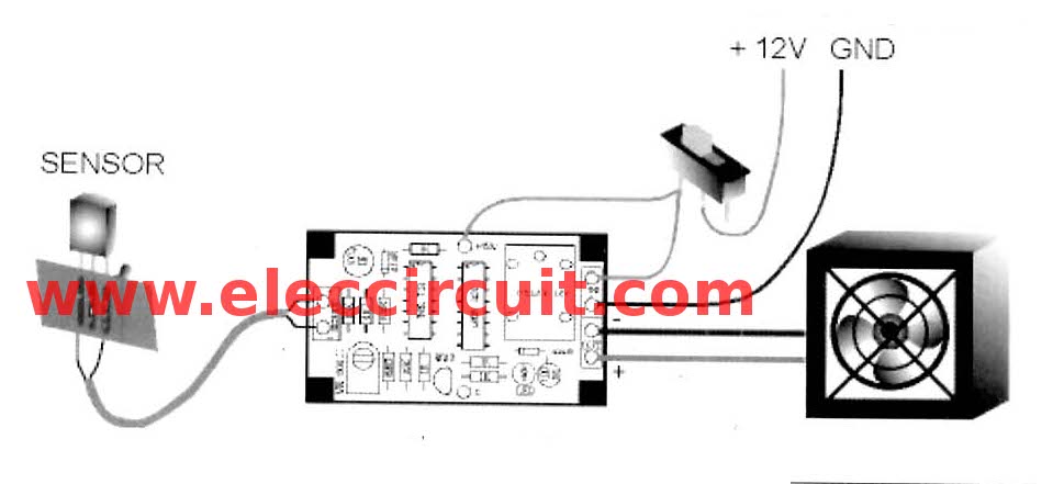
We can apply this projects now for the purpose of this project are Built cooling to the heatsink on the power amplifiers, Radio transmitter and etc. Without the need to turn the fan all the time.
Installation, the LM334Z to put it on the heatsink, by the Universal PCB Board to hold to the components with screws, and bend the pin of LM334Z to touch with the heatsink. And should be painted with silicone.
The inspection and repair.
1. When supply to the circuit, then LED glow at once, indicate that the level voltage under 12volts, VR1, Q1 error.
2. When the fan working, then temperature low down until lowest than we set, next to the fan stops at once show that IC2 damage
3. When temperature changes at pin 5 or 2 of IC1 voltage do not changes but will Equal to the power supply, the R4 damage.
The detail components
the resistors 0.25W + 5%
R1, R8, R9, R10, R11_________1K
R2________________________300 ohms
R3________________________15K
R4________________________10K
R5________________________5.6K
R6________________________4.7K
R7________________________100K
the potentiometer
VR1_____________500 ohms
The capacitors
C1, C2_______100uF 16V Electrolyte
The semiconductor
D1, D2______1N4148___ 75V 150mA Diodes
IC__________LM334Z_constant current source
and temperature sensor
IC1_________LM324_Quad OP-AMP
IC2_________CD4027_
Q1__________C9013__PNP transistor
Other parts
Relay____12V______________1 pcs.
Socket 16 pin_______________1 pcs.
Socket 14 pin_______________1 pcs.
LED______________________1 pcs.
The fan 12V________________1 pcs.
and more
More automatic fan controller circuits:
- Measurements temperature using diode
- Digital temperature meter using LM335 or LM135
- Opto-Thermo Control Relay Switch using IC-741
- Temperature detector circuit
I love electronic circuit. I will collect a lot circuit electronic for teach my son and are useful for everyone.

Plz tell me where to connect fan….???
this project can work?
please tell me,,
plz can you help me with a working circuit on battery charger with charge indicator and current
plz can you help me with a working battery charging circuit with level inducator.
please correct
the Q1 C9013 PNP transistor is a NPN transistor, right?
hello.. is this circuit working? i want to simulate it using proteus 8 software but cannot find the Q1 C9013. any transistor can replace it? last one is where are we going to placee the fan?
have anyone tried this ckt is this working???