This is Battery full charge alarm circuit for a general battery charger. It is a simplified circuit and cheap, use one transistor BC557 and display with 2 LED.
The battery that uses with a car, motorcycle or lamps lighting of fishermen. They always are a Lead-acid battery. Which each cell in the battery will have the voltage per cell is about 2.3V.
How many currents for charging
The duration of charging depends on a charging current. If the current is high, it will complete fast. But the battery is too hot. So usually, the current is lower about 10% of battery current per an hour.
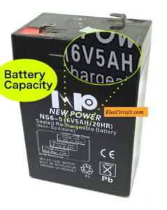
For example, I have a 6V battery. It has the battery capacity about 5Ah. So I use a constant current source about 0.5A. And it takes time about 12 hours for fully charging.
There are much 6V battery charger circuit HERE
Notice: During charging, the current will reduce continuously until the lowest is about 10mA. Which battery is near fully charged. But we cannot know that battery full or not. Because of no indicator to alarm us.
So this circuit may help us.
Two LED indicator
It has 2 LED indicator to display two status as follows.
- Green LED—show while a battery is charging. Then, it will go out if the battery is full.
- Red LED—It will light up if you put a battery in backward. Important! the battery must charge with proper polarity only.
How it works
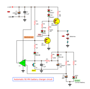
In the circuit below, is a full battery charger alarm circuit. While it is charging a battery. There are a current flows through a battery and circuit normally.
Also, a green LED lights up. And it will go out when fully charged. Because a transistors-Q1 works. And, both resistors-R1 and R2 are set a bias current to the transistor.
The Diode-D1 limits the voltage exceeds 0.7 volts.
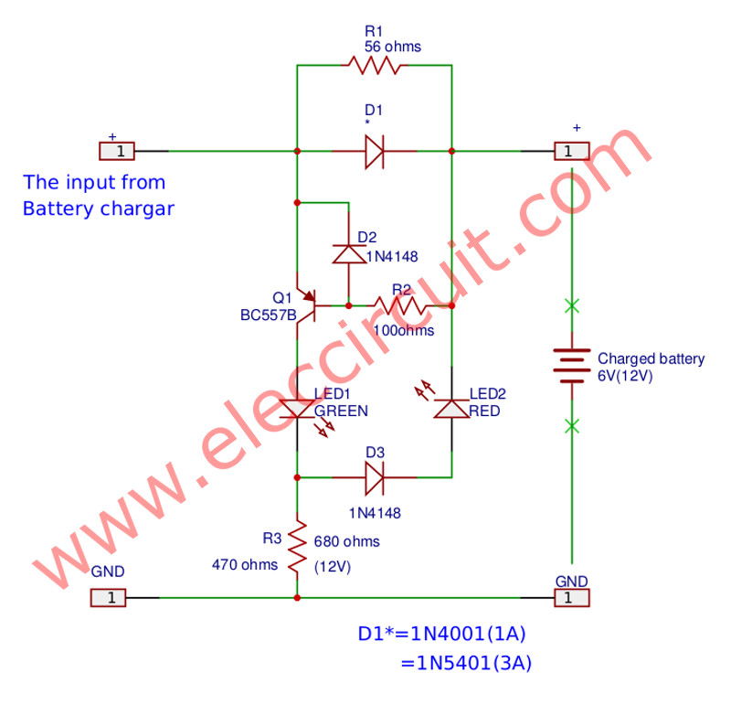
When the battery is fully charged the green LED1 goes off. Because the currents stop flowing or may flow less than 10 mA.
But the green LED1 may go out. Because the battery is a wrong polarity. The output is a short circuit. The red LED2 will glow when the wrong battery polarity.
The maximum current that this circuit can check, in between 1A to 3A. If a charging current is less than 1A. The D1-diode should be 1N4001. If the current is more than 1A but less than 3A, D1 should be 1N5401 instead.
Select battery voltage 6V or 12V—The resistor-R3 of 470 ohms will be used with the 6V Rechargeable battery. If change R3 is 680 ohms to use for 12V battery.
Recommended: Recycle Free Li-ion battery from E-waste
How to builds
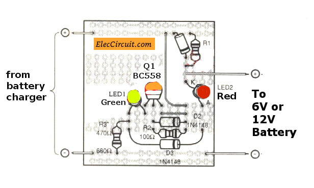
This project has a few components. So can be assembled on a universal PCB board as Figure
In the assembly circuit, Start with lowest parts first, such as a diode and then resistors and sort of high continuously.
For the devices have various polarity should be careful in the assembly circuit. Before placing these components should set the polarity on the board and match together correctly. Because If you put backward, may cause the parts or circuit damages. How to check polarity and input device.
The soldering iron is less than 40 watts. And Use of lead solder containing lead and tin in the ratio of 60/40. Including the need also to have a flux inside the lead.
After that, put the components and completely solder. To check correctness again. But if you enter the wrong position. Should use a desoldering pump or a Desoldering remover. To prevent damage to PCB.
The components List
Resistors size ¼ watts +5%
R1: 56 ohms
R2: 100 ohms
R3: 470 ohm (680 ohms)
Semiconductors
D1: 1N4001 (1N5401)
D2, D3: 1N4148, 75V 150mA Diodes
LED1: 5mm Green LED
LED2: 5mm Red LED
Q1: BC557B, 45V 100mA PNP Transistor
Others components.
The universal PCB board.
‘Automatic battery charger from a supply’ »
I love electronic circuit. I will collect a lot circuit electronic for teach my son and are useful for everyone.
Dude I try this at home. but when I change the battery polarity the green led glow and when I use right polarity of the battery to the circuit its same,the green led is glow the red led in not glowing please help me
LED2 AND D3 POLARITIES ARE WROND
Hi ABASIT,
LED2 will glow if you connect a battery in the wrong polarities.
LED2 AND D3 POLARITIES ARE WRONG
Dude I try this at home. but when I change the battery polarity the green led glow and when I use right polarity of the battery to the circuit its same,the green led is glow the red led in not glowing please help me
I have same problem red led is not glowing i check all parts is connect same to same but wrong poltery red led is not glowing
i tried this at home and correctly finish this project… the question is how long it takes to full charge 12V 5AH Lead Acid Battery in 1Amp 12V transformer? why the Green LED don’t turn off after 5 hours of charging may cause my battery to heat to much.
i need some explanation from the expert…. thanks for the kindness reply.
Hi Darwin,
You may use 0.5A current to charges for 10 hours to 12 hours. It will be full charging.
Bro I am making a phone charger using transformer of 12v 1amp as input voltage , I used ic7805 to get output 5v to charge my phone but I have an problem 🙁 to charge my phone I need 5v and 1amp as output, I am getting 5v as output But I can’t get 1amp current I’m getting lower than 1amp in output . so my phone is not charging how can I get 1amp as a output pls tell me I really frustrated pls help mee sir. I need 5v 1amp output plss tell me a solution !!
use buck converter circuit which can give output current upto 3 amp ……
LM2596
If I connect a relay collector point of 557 & the positive o/p taken from relay . Then Works or not. If it works then the circuit is fully automatic.
Pls can this circuit work for a 4volts battery?
56K resistor caught on fire when the battery was fully charged and the polarity was reversed. I threw in another diode so that the battery can’t be reverse biased, and the problem was fixed.
Hello Raj,
Thank you for visiting.
I am sorry to hear that.
And my English is poor. I may not understand your texts clearly.
Is it 56 ohms resistor? And this circuit may be suitable for a low capacity battery like 12V 5Ah.
D1 is reverse biased, so the voltage across it is 0.7V. And the current at R1 is low.
Please read https://www.eleccircuit.com/how-many-amps-hours-to-charging-battery-full/
It may relate to this.
However, this circuit I still try it. So I cannot confirm It works 100%. But I hope some people try it.
Thanks a lot.
Hi, I have a doubt. If i want to charge a 3v (2 aaa battery for example), what value of resistance should I would put?