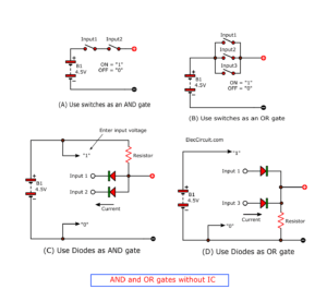
Today, we will be learning about logic gates and what their functions are. When starting to learn about digital integrated circuits, it is difficult to avoid this topic. These logic gates are the foundation for more sophisticated digital circuits.
Some may find this article boring, which could be true. Furthermore, in our experience, only a few logic gates are commonly used in actual circuits. Nonetheless, we also cannot ignore their importance, so let us get started.
What are the Logic Gates?
Logic gates are, to put it simply, a device that processes digital signals from one or more inputs and then outputs a single digital signal. Most logic gates have specific conditions that the inputs must meet before they can produce an output. A logic gate is the essential part behind all digital circuits, no matter the size or complexity.
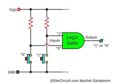
A logic gate operates with two distinct digital signals, known as bits. These signals are often represented by the difference in voltage, where high voltage may be referred to as “1” and low voltage as “0.” In a normal circuit, the “1” bit is usually set at the input voltage, whereas the “0” bit is ideally at GND, 0V, or disconnected (open-circuit). These two bits are also known as “high” and “low.”
Single-Input Logic Gates
These are simple gates with only a single input and an output. There are only two logic gates of this type, and they are certainly straightforward in their operation.
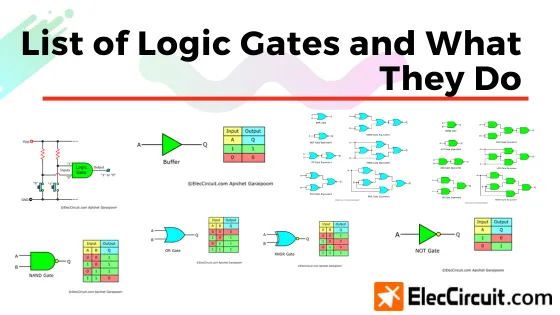
Buffer (Digital Buffer)
A buffer is the simplest of the logic gates if you can even call it that. It is a device that reproduces the logic input it receives and outputs that logic. For instance, if a buffer receives “1” input, it will output “1” as well.
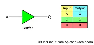
Nonetheless, a buffer is often used not for its “logic” but for its properties of isolating its input from its output. Unlike a wire that connects one circuit to another, a buffer reproduces the input from one circuit and outputs it to the other. As a result, the circuits at the buffer’s input and output are not in direct connection.
NOT Gate (Inverter)
A NOT gate—also known as an inverter—is a device that reproduces outputs opposite to those of its input. Therefore, if the input is “1,” the output would be “0.” The term “inverter” came from the fact that a NOT gate outputs the inverted logic of its input.
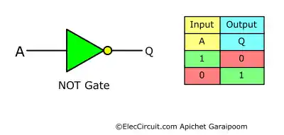
An inverter is a very common addition in electronics. It is a basic building block for many digital circuits.
Multiple-Input Logic Gates
Multiple-input logic gates, as the name suggests, have multiple inputs. Today, we will only look at two input variants of the logic gates: input A and input B, as they are the simplest. However, it was noted that these logic gates would function the same with more than two inputs.
AND Gate
An AND gate is a simple logic gate with multiple inputs. It is a device that outputs “1” only if both input A and input B receive a “1” logic value. So, for example, if input A receives “1” but input B receives “0,” the output will be “0.” The truth table below will help you better understand the function of the AND gate.
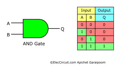
An AND gate is also known as a logical conjunction.
NAND Gate
You can think of a NAND gate as being the opposite of an AND gate. It is a device that will output “1” when input A and input B do not receive a “1” logic value. Another way of remembering a NAND gate is that it is a “NOT AND” gate, outputting “1” when both inputs are not equal to “1” and outputting “0” when both inputs are “1.” The truth table below may help you understand.
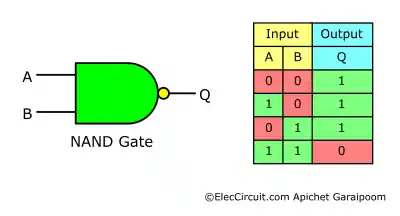
A NAND gate may also be known as a logical non-conjunction or alternative denial. It is a negation of a logical conjunction (AND).
OR Gate
An OR gate is a device that outputs “1” if any of its inputs receive “1” logic. To put it another way, an OR gate outputs “0” if both inputs receive “0” logic and “1” if either input A or input B receives “1.” The input A or B has to be “1” for the output to be “1,” hence the name “OR” gate.
In the case that both input A and input B receive “1” logic, the output would still be “1.” This is because, logic-wise, if “A and B = 1” is true, then “A or B = 1” is also true. This starts to get complicated, but the truth table should be able to help clear things up.
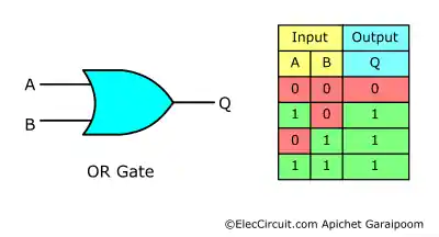
An OR gate is referred to as a logical disjunction, which is the dual of a logical conjunction (AND).
NOR Gate
A NOR gate is the opposite of an OR gate from above. It is a device that outputs “1” only if both inputs A and B receive “0” logic. Whereas if one or both of its inputs receive “1,” it will output “0.” For the output to be “1,” neither input A nor B can be “1.”
Akin to an OR gate above, both inputs of a NOR gate receiving “1” are equivalent to one input receiving “1.” So if any of the inputs receive “1” at all, the output will always be “0.” Their truth table helps us see the opposite effect of an OR and NOR gate.
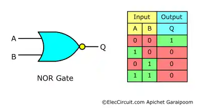
A NOR gate is a logical non-disjunction or joint denial. It is a negation of a logical disjunction (OR).
XOR Gate
An XOR gate is functionally similar to an OR gate. The difference is that if both of its inputs, A and B, receive “1,” it will now output “0,” while an OR gate would output “1.” So, an XOR gate is a device that outputs “1” only when its two inputs differ from one another, as shown in the truth table below.
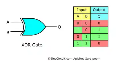
An XOR gate is an abbreviation of an “exclusive or,” or an exclusive disjunction. It counts exclusively the disjunction and not the “all true”.
XNOR Gate
An XNOR gate is a device that outputs “1” when both of its inputs receive the same logic, either “1” or “0.” Instead of outputting “1” only when both inputs receive “0” like a NOR gate, an XNOR gate outputs “1” when both inputs simultaneously receive either “1” or “0.” The truth tables clearly show the difference.
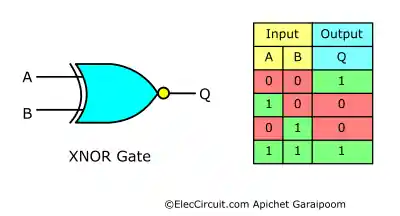
An XNOR gate is also known as a logical biconditional, which is the negation of an exclusive disjunction (XOR). Biconditional means two conditions, either all true or all false.
Equivalent Logic Gates From NAND or NOR Gates
NAND and NOR gates differ from the rest of the logic gates in that they are functionally complete. This means that NAND logic and NOR logic alone can be used to express every logical expression. As a result, we can use these two gates to simulate any other logic gate. The illustrations below demonstrate how to connect them to perform the function of any logic gate.
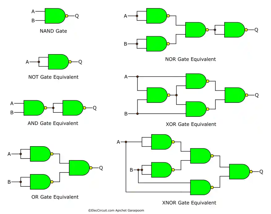
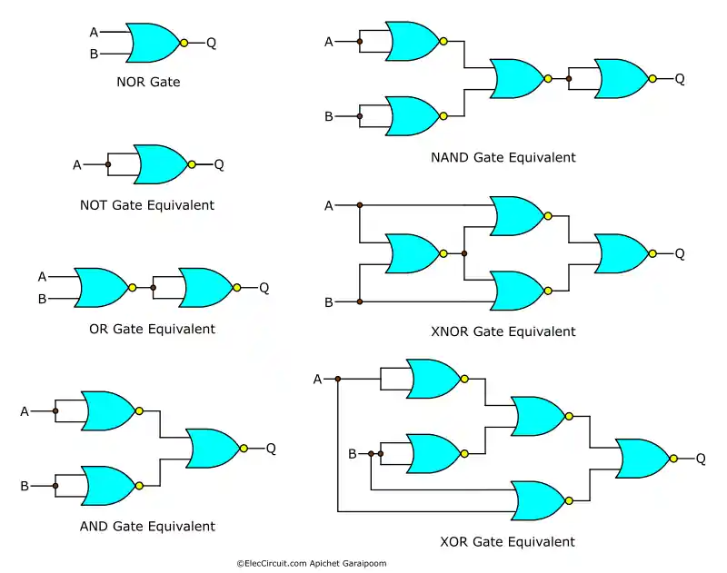
This comes in very handy when building a digital circuit since we only need one type of logic gate to substitute for any other type of gate. The NAND and NOR gates are also referred to as “universal logic gates.”
Next time, we will examine how logic is applied in circuits. These will include common digital integrated circuits (ICs), as well as how to utilize the logic gates inside of them.
Our member area also contains this content.
You can download it in PDF format with larger images, while the content remains the same.
I appreciate your support.

I love electronics. I have been learning about them through creating simple electronic circuits or small projects. And now I am also having my children do the same. Nevertheless, I hope you found the experiences we shared on this site useful and fulfilling.