So we need a 12V power supply circuit for a DC water pump that requires a 12V 2A DC input. In this case, we could use a regular unregulated power supply since the water pump is just a DC motor.
The upsides for this circuit are that it only requires a few components, is very durable even after 15 years of use, and is relatively safe from a short circuit.
Compared to normal cheap switching mode power supplies that have more failure points due to their high complexity, are less durable because of their small size, and are prone to short-circuiting or leaking during their operation.
How Would the 12V Power Supply Circuit Work
We will start by looking at a block diagram of a working principle of unregulated power supply This block diagram is quite easy, and we can use it as a broad process-by-process guideline for circuit design.
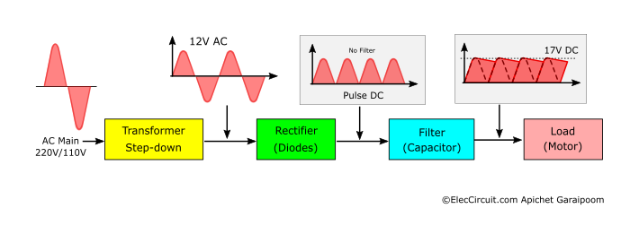
- The step-down voltage transformer converts high-voltage AC mains to a lower 12VAC at the same 50Hz or 60Hz frequency. This transformer is also essential in determining the output current later on, so we need to choose carefully.
- The 12VAC then goes into the diode rectifier, which results in a pulse DC with a frequency twice as high as the original AC at 100Hz.
- The pulse DC then flows through the filter capacitor, coming out as a relatively smooth 17V DC.
- Lastly, this DC voltage flows to the load. When the load pulls electricity from the circuit, it causes the capacitor to discharge and the output signal to turn into a pulse DC again. If we measure the output voltage, we will see that it is about 12V to 15V DC, depending on the current the load pulls.
Turning Block Diagram Into Power Supply Circuit
Now we will choose components according to the block diagram above and then put them together into a working circuit, as shown below.
Full-wave Rectifier
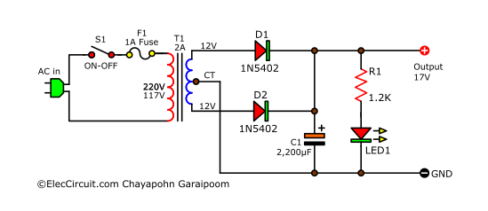
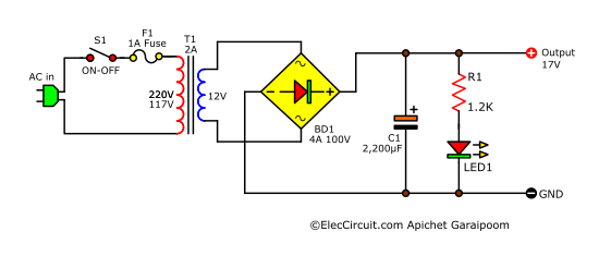
We chose the full-wave rectifier because it only uses two diodes and offers good enough efficiency. In the circuit above, the AC main voltage (AC100V/220V) flows into the circuit through the S1 power switch and the F1 fuse to protect against overload current.
The Transformer
If our load pulls a current of 2A, we would also need a transformer that can withstand 2A or more; the higher the current it can support, the better. The transformer also needs to be able to deliver constant current, and it has to be one with a center tap on the secondary coil.
The Rectifier
As for the rectifier, we chose the 1N5402 as both D1 and D2. It is a low-cost diode with a high forward current of 3A and a continuous reverse voltage of 200V.
The Filter Capacitor
The DC filter for this circuit is the C1, and we can calculate its capacitance using the following formula.
C1 = IL ÷ (2 × F × Vrip)
IL is the load current, which is 2A max.
F is a DC pulse frequency, which is twice that of AC. For example, in the EU it will be 50Hz times two; in the US it will be 60Hz times two. In our case, it is 100Hz
Vrip is the ripple voltage. A normal power supply circuit usually has a ripple voltage of approximately 10% of DCV. But in this case, we will use the ripple voltage of 30% of our 17V DCV, which is 5.1V.
Substitute the values in the formula:
C1 = 1 ÷ (2 × 100 × 5.1V)
C1 = 1,818.18µF, but we will use 2,200µF 25V instead.
Which is enough for our load; even when it pulls the maximum amount of current, the Vrip still remains at 11.9V (17V – 5.1V).
Lastly, the LED1 is a power-on indicator, and R1 limits the current for the LED1.
Assembling the 12V Power Supply Circuit
This 12V power supply circuit is quite easy to put together. So, this time, we will not use a PCB; instead, we will use a hammer to drive nails into a wooden board and then solder the components onto it.
But first, we must prepare the components in the list below.
Components List
T1: 12V CT 12V, 2A transformer
D1,D2: 1N5402, 3A Diode
C1: 2,200uF 25V Electrolytic capacitor
R1: 1.2K 0.5W Resistors
LED1: LEDs as you like
S1: ON-OFF switches
F1: Fuse 1A
Copper wires and nail 0.5inch, AC line power
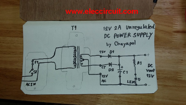
Firstly, we draw the component layout for the circuit on paper and glue it to the board.
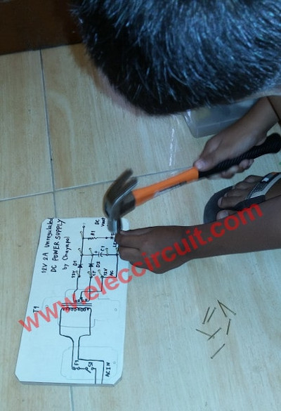
Then, we use a hammer to drive nails into the predetermined spot.
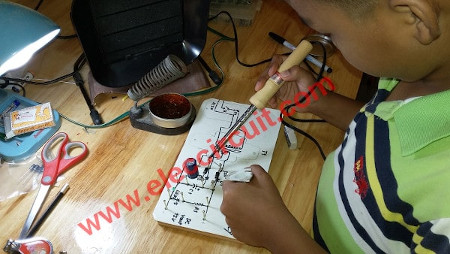
After that, we solder every component and wire to the nails.
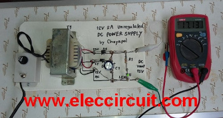
After we complete the assembly of the circuit, we measure the voltage at the output; it reads 17V without load.
Then, apply the DC pump as a load, as shown in the video below.
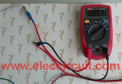
Then, we measure the current of the load, which is normally about 0.9A.
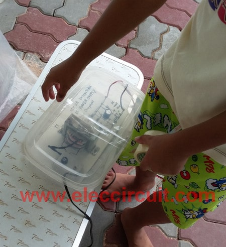
This 12V power supply circuit is deployed outdoors, so we put the entire thing into a plastic box to protect against the elements.
Alternative Transformer and Bridge Rectifier
However, if you cannot find a transformer with a center tap, you can just use a normal two-terminal transformer and then change the rectifier to a diode bridge instead. However, the bridge rectifier should have a current rating twice that of the transformer. In this case, a 100V 4A bridge diode.
12V 3A Power Supply Circuit
Nowadays, Bluetooth receiver amplifiers are inexpensive and sound relatively good. They are suitable to be installed in a car because of their small size, but using them in a small room is also a good idea.

Photo by Hosyond Store: https://amzn.to/3DoSkUI
Powering them with a car battery introduces next to no noise at all. However, when using a 12V 3A wall adapter, we would hear noticeable increases in audio noise.
The following power supply will help alleviate this problem. It only operates in the low-frequency range; therefore, it will have very little noise.
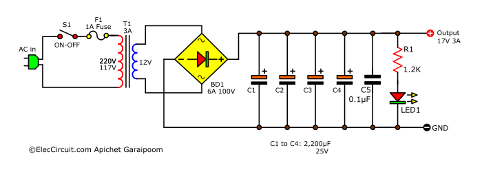
Now that the load current has increased to 3A from 2A in the previous circuit, we would also have to increase the current of the transformer to 3A and the diode bridge to 6A.
Finding the value of C1
As for the capacitance of the filter capacitor C1, we have to decrease the ripple voltage (Vrip) down to 10% of VDC. So if VDC is 17V, Vrip is 1.7V.
C1 = IL ÷ (2 × F × Vrip)
IL = load current of 3A
F = DC pulse frequency of 100Hz
Vrip = 1.7V
C1 = 3A ÷ (2 × 100Hz × 1.7V)
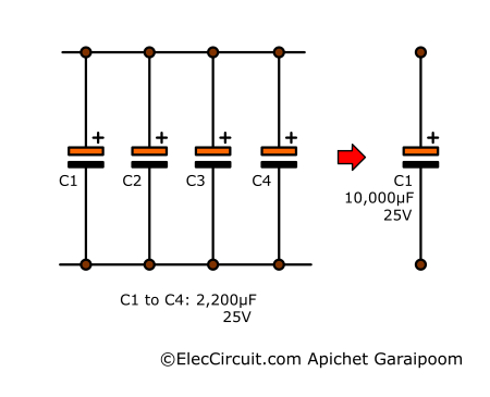
C1 = 8,823uF. But this value is not available for sale, so use the method of bringing 4x 2,200uF in parallel to increase the capacitance.
However, you can also use just one 10,000uF 25V if you happen to have one.
Noise Filter
Sometimes we may hear some noise while these sound systems are on, such as the sound of a motor running. It is a high frequency mixed with the DCV level. It has a higher frequency than Vrip but has a very low amplitude. However, it is still annoying.
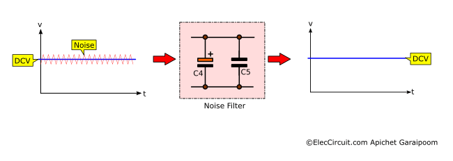
The noise signal has a relatively high frequency and is combined with a DC voltage. It may appear insignificant, but after passing through a high-gain amplifier circuit, it will become much more noticeable.
The solution is to add decoupling capacitors (C5) in parallel with the filter capacitor (C4).
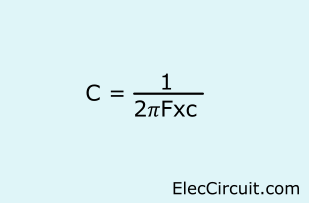
We can calculate the value of C using the formula below.
F is the frequency of the noise signal.
XC is the electrical resistance of the capacitor when used with AC, we set it to 1Ω.
F is the noise frequency. We start with 10MHz or 10,000,000 Hz.
C5 = 1÷(2×𝜋×10,000,000×1)
C5 = 0.0159µF
We will use 0.022µF instead.
Now let’s rearrange the formula, isolating the XC on one side, and find its value.
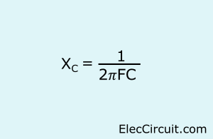
XC = 1÷(2×𝜋×10MHz×0.022µF)
XC = 0.72Ω
But if that still doesn’t work, we will try increasing the capacitance another 10 times, which is 0.22µF, which will have a lower frequency response of 1MHz.
In this case, we use 0.1µF, so the response to the frequency is around 500KHz, which is good and reduces noise.
Conclusion
We can make a 12V power supply circuit ourselves; it is simple, works well, and is durable. If you need a higher current, you can try calculating the components and trying it appropriately.
GET UPDATE VIA EMAIL
I always try to make Electronics Learning Easy.

I love electronics. I have been learning about them through creating simple electronic circuits or small projects. And now I am also having my children do the same. Nevertheless, I hope you found the experiences we shared on this site useful and fulfilling.
I remember doing this as a kid. My dad had some wood and some brass tacks. I was curious to what commonly available metals I could get solder to “stick” to. I found out brass tacks took solder easily, so I built a siren with a schematic I found using those brass tacks and wood.
Hello James,
Thanks for your feedback.
Your experience makes me smile and feel very warm.
The Electronics is not obsolete. It is a fun activity for the family.
Unfortunately, now. My son does not like electronics.
But I will prepare the content and learn for him.
I have believed that he will come back to love electronics again.
Have a good day.