If you are an electronics beginner. It may be too much difficult for you. In the design of the BCD signal generator circuit by pressing a key. Here is how you make a keyboard encoder circuit for 16 keypads.
Your life will be easier. You use this circuit below. Because it consists of a single IC
and a few components, three capacitors.
How this circuit works
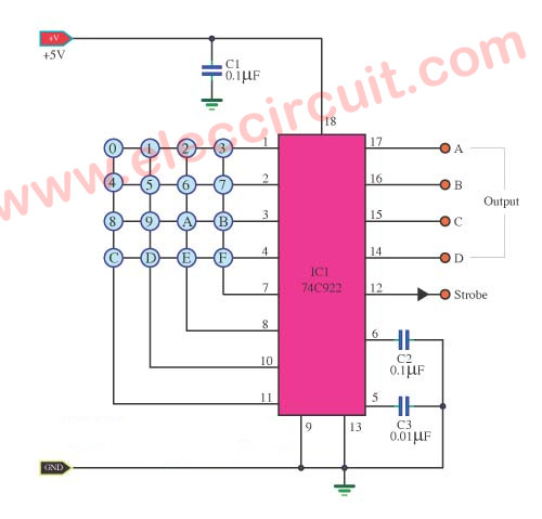
First of all, connect all input keys in the matrix model. It consists of row and column. Which each row and column have four rows.
So It can make the code number in 16 stage from 0-15. The binary code output to pin 14,15,16,17 respectively.
When we press a key. Then, a pulse signal comes out of pin 12 in each time. That pulse signal has a short time in only one cycle. We call it that “Strobe signal” to control other circuits outside there.
When we leave a finger from the pushbutton switch. The output binary at pin 14 to pin 17 will still hold in all time. Until we press the pushbutton new again. The output binary will be turning follow we press that button as above.
The keypad switches are used as a matrix. Which you may make them by yourself. By the positions of the switch in new requirements.
Keep reading:
Logical guessing game circuit
But buying in a store near you. It is a better convenience for us. The cost of an instant keypad is cheap such as 4×4 Matrix 16 Keys Button Keypad.
The number of keys is used. Maybe set to 0-9 keys. Then, leaves AF is blank only.
The voltage power supply applies to the circuit is 5V. Because of the digital circuit.
Key Code Lock Switch Circuit
Parts you will need
IC1—74C922N, keyboard encoder, Quantity: 1
C1,C2 = 0.1µF 63V, Ceramic Capacitors,Quantity: 2
C3 = 0.01µF 50V, Ceramic Capacitors,Quantity: 1
In the building this circuit. We can assemble all electronic devices in the perforated board as below. For key switches, we do not design it into the PCB.
But you can design or you use an instant keypad as you want.
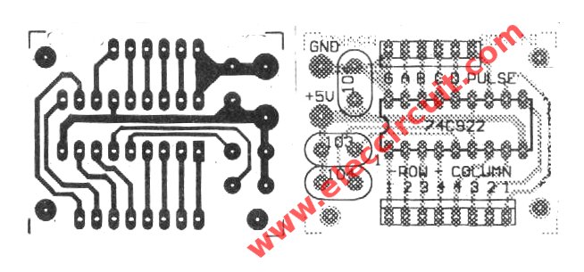
Figure 2 The PCB layout and the components layout of this projects.
GET UPDATE VIA EMAIL
I always try to make Electronics Learning Easy.
Related Posts


I love electronic circuit. I will collect a lot circuit electronic for teach my son and are useful for everyone.
*******This is a rough translation of the original description. If I messed it up anywhere, please let me know.
The design of BCD signal circuits that are controlled by pressing a key is difficult for a electronics beginner.
This circuit is an attempt at a simple explanation. It is versatile, because the circuit is designed using a single IC.
Please look at the circuit shown in Figure 1.
The key input circuit is connected in the matrix format, with the signal provided by pressing the input buttons which produces a matrix address from the Row and Column, based on 4 rows and 4 columns. These inputs set the appropriate Internal register of the IC to a value. Keys not pressed are not considered in the matrix.
The binary code output goes to pins 14,15,16,17 respectively. Pin 12 is the strobe key. It enables the output. The output is short lived and the oscillator that produces the strobe signal is monostable, so one output per press.
[email protected]
Hello, Rory Starkweather
I feel good that you tell me. It is true. This content is not readable at all.
I will try to rewrite it.
I need more knowledge in field of study
how to input the second number and stored.