If you would like to build a HI-FI power amplifier project that power output size of about 30 watts to 50 watts or 75 watts at 8 ohms loudspeaker, and is high-quality sound and easy to build (not too many components). We recommend you use TDA2050 class AB OCL amplifier circuits.
Below that builds with the integrated circuit, PCB layout and no need for any customization. Parts used in this circuit are easily available in most of the local markets.
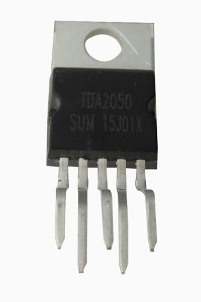
TDA2050 datasheet
The TDA2050 is class AB audio amplifier. Its high power capability the TDA2050 is able to provide up to 35W true rms power into speaker 4 ohm load at THD =10%, VS =±18V, f = 1KHz and up to 32W into 8ohm load @THD = 10%, VS = 22V, f = 1KHz.Moreover, the TDA 2050 delivers typically 50W
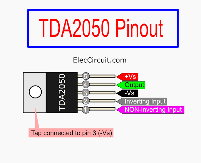
Pinout
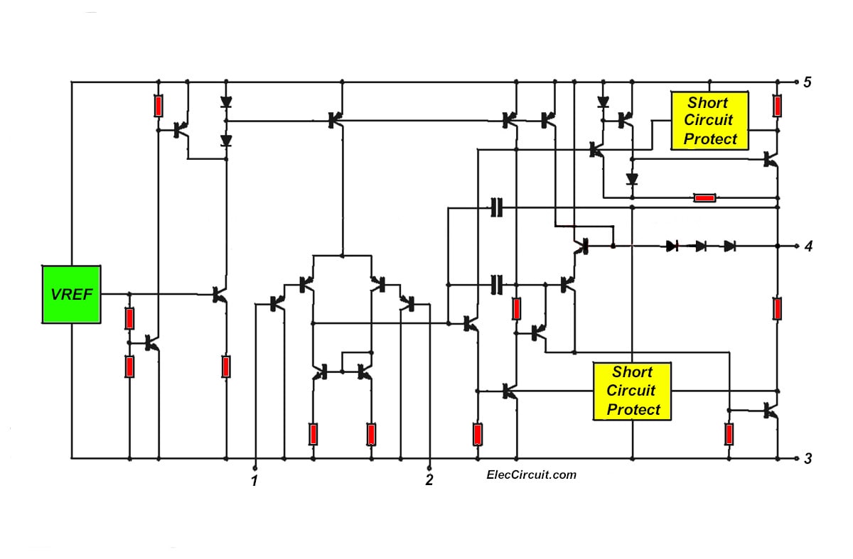
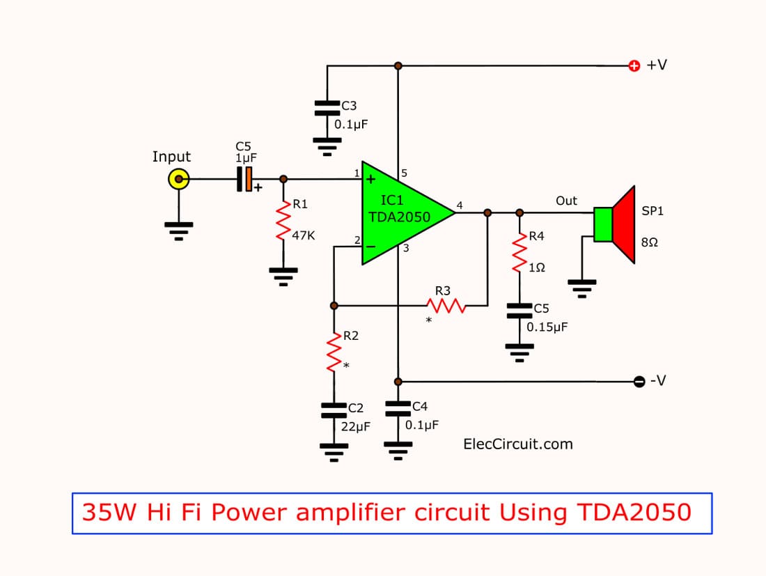
The schematic diagram
The music power into the 4-ohm load over 1 sec at VS=22.5V, f = 1KHz
May take an interest want to try build already, try out this circuit use voltage Vcc +/- 25V.
Here is the TDA2050 I found on Amazon Read more (affiliated link)
35W TDA2050 Amplifier Mono
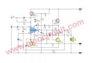
I know you want to see an example circuit. Here is a simple circuit.
Ready to get started?
Look:
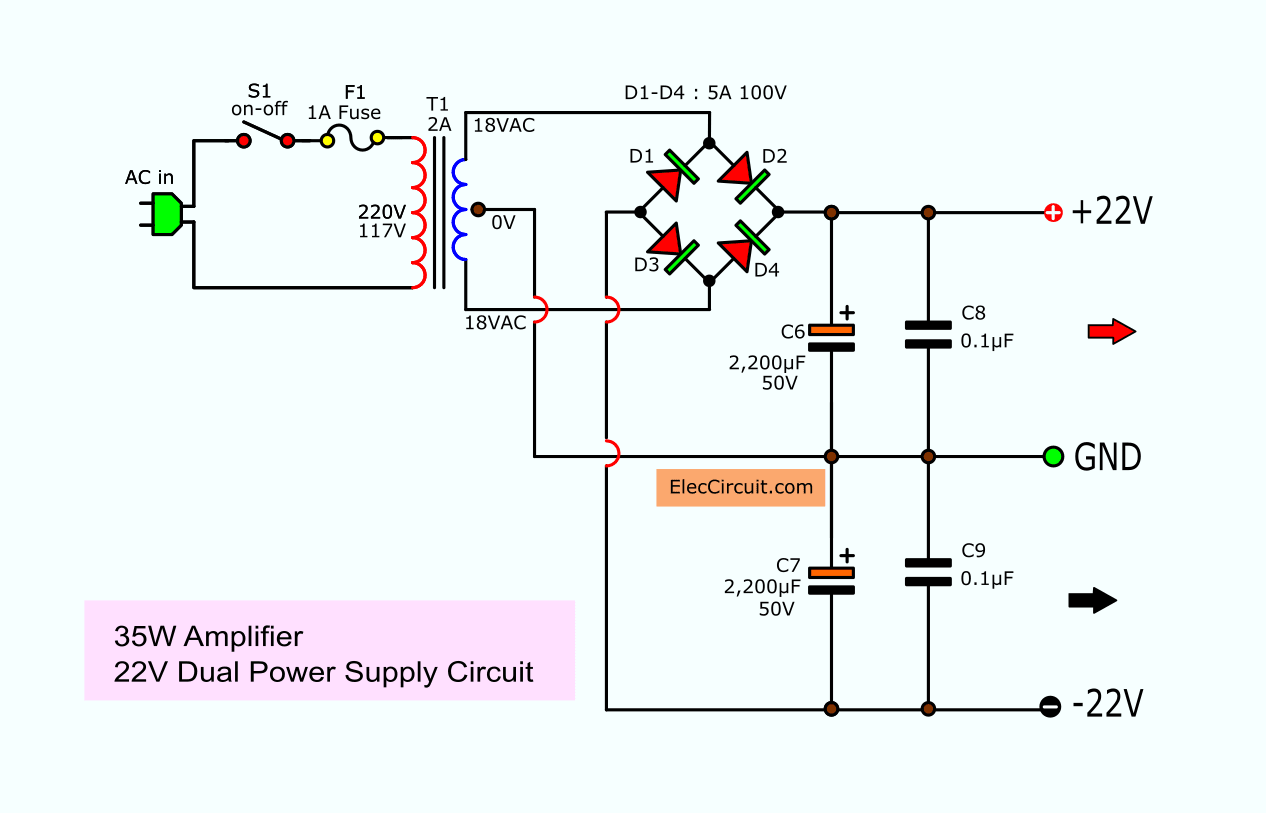
22V Dual Power Supply circuit for 35W amplifier.
Parts you will need
Electrolytic Capacitors
C1: 0.47 to 22uF 50V
C2: 22uF 35V
C6, C7: 2,200uF 50V
Mylar or Ceramic Capacitors
C3,C4: 0.1uF 50V
C5: 0.15uF or 0.1uF 63V
C8, C9: 0.1uF 63V
0.25W Resistors, 5% tolerance
R1, R3: 47K
R2: 1 to 3.3K or 680 ohms
R4: 1 to 4.7 ohms

PCB : 35W Hi-Fi AUDIO POWER AMPLIFIER by TDA2050

on PCB : 35W Hi-Fi AUDIO POWER AMPLIFIER by TDA2050
50W-75W Stereo power amplifier using TDA2050
We used the TDA2030 to build many power amplifier projects, but they have lower power than 30 watts.
Today, we try to use the TDA2050, which has the output power about 50 watts that shape and easy to use as well.
This project is stereo that easy to builds can adjust volume, tone and balanced sound.
First of all, we look at the circuit diagram below.
This circuit with a high current so takes low voltage 25V similar the normal 30 watts amplifier.
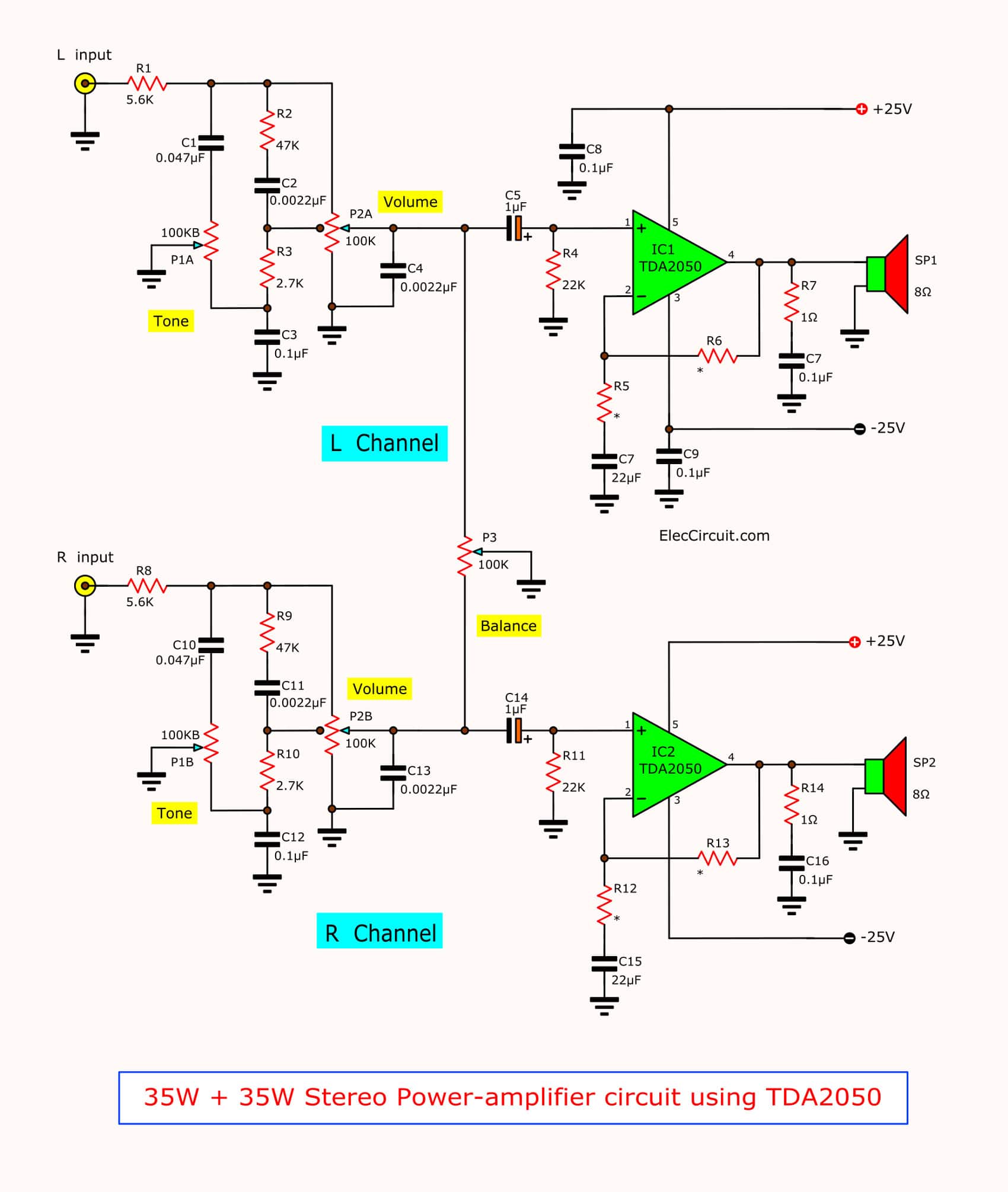
Figure 1: the 35W + 35W stereo power amplifier circuit using TDA2050
We should use the 25V CT -25V high current power supply circuit with RFI filter system. Which have 4 x 2,200uF 50V are connected together in parallel.
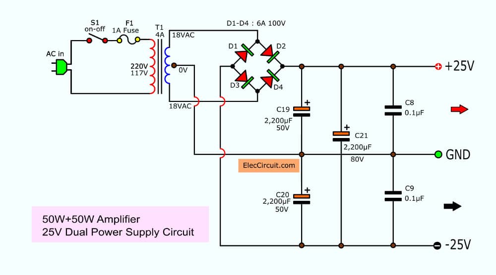
Figure 2: the 25V CT -25V Dual power supply of this projects
We can boost up power output to 75 watts by the same voltage power supply.
In the circuit, we use both transistors 2N3055 NPN types and MJ2955 PNP type to increase current up.
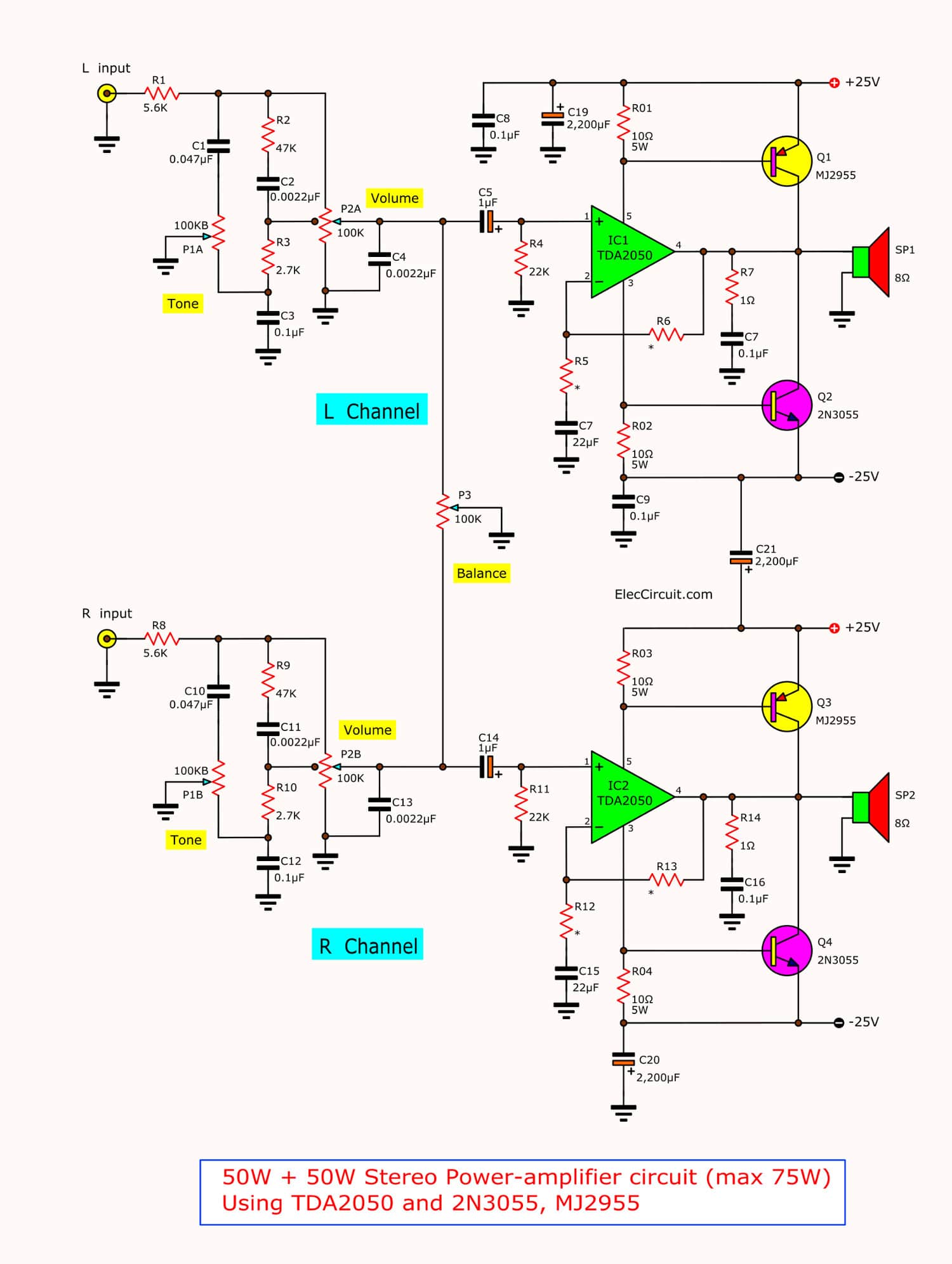
Figure 3: the 50W + 50W (Max75W) stereo power amplifier project using TDA2050 and 2N3055-MJ2955
How to build
We do not need to explain a lot. Lets to build this project better.
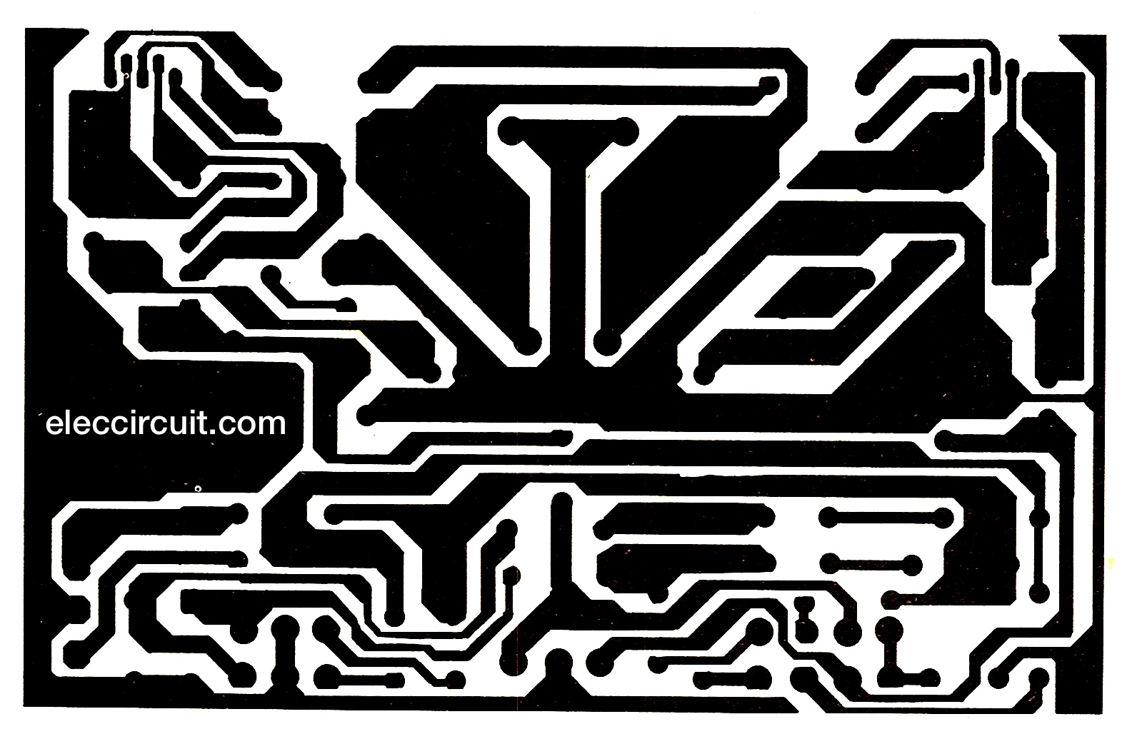
Figure 4 the PCB layouts.
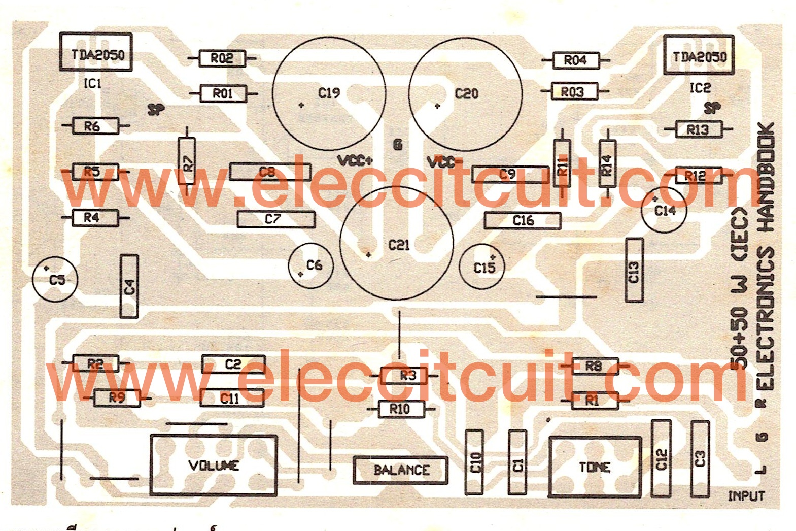
Figure 5 the component layout of this projects
Parts you will need
IC1, IC2: TDA2050
0.5W resistors, 5% Tolerance
R1, R8: 5.6K
R2, R9: 47K
R3, R18: 2.7K
R4, R11: 22K
R5, R12: 680 ohms
R6, R13: 22K
R7, R14: 1 ohm
R01, R02, R03, R04: 10 ohms 5W Resistors
Ceramic Capacitors
C1, C10: 47nF(0.047uF) 50V
C2, C4, C11, C13: 2.2nF(0.0022uF) 50V
C3, C7, C8, C9, C12, C16: 0.1uF 50V
Electrolytic Capacitors
C5, C14: 1uF 50V
C19, C20: 2,200uF 50V
C21: 2,200uF 80V
P1: 100KB, Dual Audio Potentiometer
P2: 100KA, Dual Audio Potentiometer
P3: 100K, Audio Potentiometer
Q1, Q3: MJ2955, PNP transistors
Q2, Q4: 2N3055, NPN transistors
Note:
On Figure 1 and Figure 3
R5,R12: 680 ohms, 0.5W Resistors 5%
R6,R13: 22K, 0.5W Resistors 5%
You can use TIP3055 instead of the 2N3055 and TIP2955 instead of MJ2955 because easy to use.

I love electronics. I have been learning about them through creating simple electronic circuits or small projects. And now I am also having my children do the same. Nevertheless, I hope you found the experiences we shared on this site useful and fulfilling.

hello,
I’m looking for a circuit for a simple 3 phase bldc -controller .
without mikroprozessor.und without hall sensoren.12-24 volts.5 ampre .
circuit : clock generator, 3 phase with 4017cmos , and 3 power stages.
many greetings
walter
Thanks.
The TDA2050 is a very well designed power amplifier. However, in the foregoing, there are various suggestions regarding enhancing its output power. I have found that the TDA2050 can sink/source 5 Amps maximum. If built into a bridge configuration and driving an 8 ohm speaker, the peak power for such a configuration is 5 x 5 x 8 (i.e. I*I*R) which is around 200 Watts peak, namely around 130 Watt RMS into an 8 ohm load. Such a configuration works well in practice, both with split rail power supplies and with single rail power supplies. The advantage of a bridge configuration is avoiding a need for the output electrolytic capacitor which, if too large (i.e. grater than 1000 uF for supply rails in excess of 40 volts total from VS+ to VS-), and also not by-passed via blocking diodes to the VS supply rail(s), can cause failure of the TDA2050 (see its data sheet for more guidance).
In operation, the TDA2050 provides very low distortion over most of its operating range, but needs to have a 022 uF plate ceramic capacitor strapped across its VS- to VS+ pins (as close to the IC as possible), otherwise it has a tendency to oscillate parasitically at a very high frequency (e,g, several MHz).
Hope above is useful to you !
Kind regards
Dr Tim
Thanks
The details are extremely helpful to me for my diy projects and actual products and system designs
Typos in my previous comment:
0.22 uF plate ceramic strapped as close as possible to IC to avoid parasitic oscillations.
Note that the TDA2050 is rated at 50 volts absolute maximum supply rail, so running it on +/- 25 volts (as suggested above by other contributors) is perhaps a bit risky; LM1875 can be run to 60 volts total supply rail, but its output current is limited to 4 Amps. My experience with many many TDA2050 that I have used, is to limit the total supply rail to 45 volts maximum (providing a few volts safety margin).
Kind regards
Tim
Since 2012, TDA2050 is discontinued, only non-approved vendors sell them, and every one I buy is a fake. The price is very low, but maximum current is only 3 amps, and voltage swing is also limited, output can’t swing within 5 volts of supply rails. That is not even as good as the TDA2030. Too bad ST discontinued them, but with all the fakes it must have diluted sales and also created upset customers who thought they were buying real parts.
Please help! I used two electrolytic capacitors each filtering the supply to power amplifier;and the out put of these two capacitors are +18 and -3 how I can solve these one is there a problem with my power amp?
what capacitor in 35W tda2050 apm. mono “c5-100(150)nf”
what capacitor in 35W tda2050 apm. mono “c5-100(150)nf” ?
I guess that was 100nf (104)..or 100 —>150nf(104) —> (154).
I have try this curcuit…It preety cool..U can just swap between TDA2030A and TDA2050 without change anycompenent..Resistor and caps..It working for me..I have test it on 12Vdc,24Vdc and 36Vdc..3A.But on single supply setting.. 🙁 R5 i use 150nf..
May you kindly assist with a schematic. I wanna try it but I wanna make sure I do something which is tested and working
TDA2050 +3055/2955 75W not working..Can someone give the right diagram base on this 3 same chips?For dual and single supply…?
I already blown 2 TDA2050 and 2 TIP3055 coz by overheat without any sound aka .bzzz..sound only by following the diagram above.Next time please show the diagram that working *only*.
I have make TDA2050 + TIP3055/TIP2955 curcuit on single supply setup.I test it on 24V 3A…it ok..but after i increase the voltage to 48V TIP2955 blow up while play music (Vol at 60%)..I already blow 2 TIP2955 at same condition…The heat sink …super large lol..T2955 blow just like that after 40-50 scnd..I touch all the chip..I still on normal load heat condition..just warm a little bit..So actually what is the problem that make TIP2955(PNP) blown?
the schematic for adding power resistors looks like a short circuit!!
I already success make tis poweramp tda2050/TIP3055/TIP2955.Single supply configuration.The sound wallaaa..kickasss..make glass windows on my room shaking like it gonna crackup :!!!
i change the resistor 10Ohm to 3.33Ohm by adding 10Ohm/2Watt x 3pcs (3.33Ohm/6W).Sound super clean..On 40% volume u dont hear any bzzzzzz sound if theres no music is loadin..It keep silent..
Send me your circuit diagram you have used
Diagram please
nice post
Hey guyz!, I have tried the circuit above{50w+50w}, works perfectly, but the other one{75w+75w} failed to work. Can anyone correct this please…
Ok now i have success make this TDA2050 + TIP3055 and TIP2955 power transistor on single supply curcuit.The sound awesome..Kickass sound..:D
The diagram for single supply ;
https://mega.nz/#!zt1VzbhI!lpTf14xxaoD8j77MEURhsyCLks3NdZUjGxaq6lqHwAA
Just make sure to use big heatsink and better dont use any isolated on tda2050 for pure direct heat transfer.Isolate the 2 pcs power transistor only.On this setup TDA2050 will get heat more faster then default.Almost 3x more faster generate heat..
Plis i made dat of 35wat & also a bass/treble to at as pre-amp but when i connected it, it worked but the sound was not clear & it’s making a buzzzzz noise. I am a beginner what do i do? Thanks.
the amp i made works very well when it gets signal from phone, but when i conect dvd play the sound becomes low and not clear
How to connect the wires from the circuit R3,R2,C5 and ground in the potentiometer? since they are four different connection and the potentio has only 3 pins
huhuhu . 50 + 50 doesn’t work. I used the pcb design they gave. It produced bzzzz sound.
Brother where you used Q1,Q2,Q3 and Q4?
so good
I wanna ask about split supply of tda2050
In the datasheet they montionned that the max power is about 25v
If we use +-25 v its like we powred the circuit with 50v noo???
How much voltage and power i shoud use in ac that gives me 25v dc any idea post comment or email me
hay its a nice project enjoying TDA2050’s sound right now .For 75w resistors at the base should be 2.2ohms 2w for better performance
Replace 3055 and 2955 with tip 147 & tip 142 / 5200&1943 ….for best results
Hello Waqar Ahmed,
You should replace them with TIP3055 and TIP2955. For TIP147 is Darington transistor. I think they are too much gain but not high power.
how can i purchase your assembled kit?
can you help me for that,
This are knockoff parts not real TDA2050 Short the output and they will go poof. Stay away from junk parts. The original is sadly no longer available.
Thanx sir , sir l have a question i made a 200w amplifier with tda 2030a and tip35 and tip36 transistors can i use 4700uf capacitors instead of 10000uf or 20000uf capacitors ??
Hi Ness,
Yes, you can. You may use many 4,700uF capacitors in parallel.
For example, 4,700uF x 2. They can instead of 10,000uF. Or
4,700uF x 4 instead of 20,000uF.
However, if you use only one 4,700uF. It makes low bass than high capacitances.
Ic1875 ka pcb circuit diagram +schmetic diagram batay
Hello Rk Singh,
Thank you that you are interested this circuit. I don’t have service to sell the PCB.
Am still growing in this field but leaning more from you guys
Hello, Charles ongale,
🙂 It is so good to hear that.
If you have any ideas please tell us.
We love to learn more about electronics.
Thanks
Very good circuit…i want design it..
Help want to make TDA 2050 stereo amp with balance control but don’t understand the wiring on volume controls c2 and r3 AND c11 and r10 to volume pots. Can any explain.
Thanks