This is a TV test pattern generator circuit with a wireless model.
The components in assembling circuits not difficult can transmit signal in wireless are video and audio As horizontal line. Along with tone.
Using the power of just one 9V battery.
This circuit is very suitable for TV repairman or those who want to test that your television, can use also use it? by it will send video signal in VHF (very high frequency) band.
Which it is a range for use channel 5, 7, 9 and 11.
The image appears on the TV screen is a horizontal straight line with Tone out to the speaker.
The circuit principle
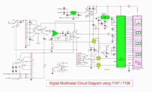
In Figure 1 is the TV test pattern generator with the wireless model will see that is basic astable circuit connected with the modulator circuit there.
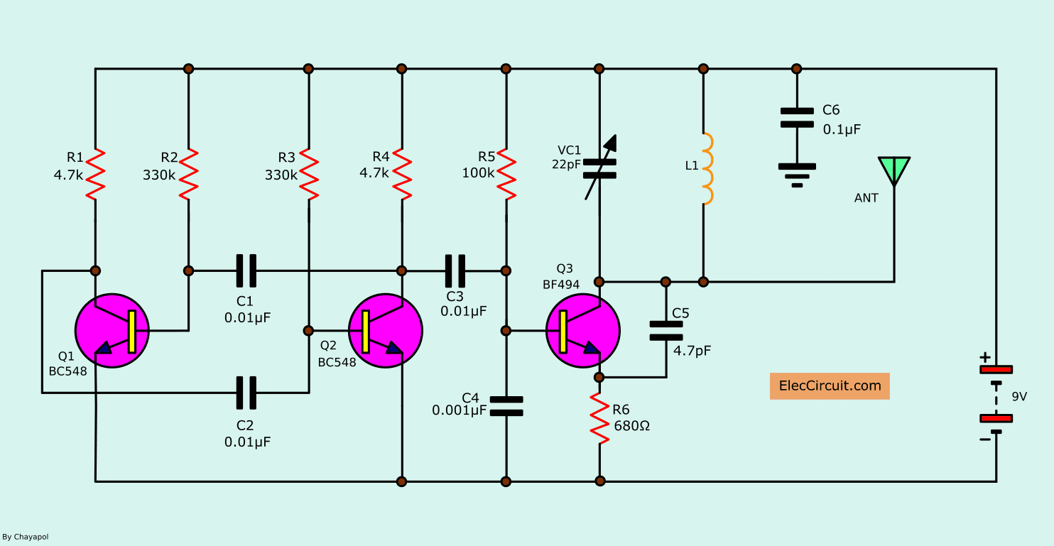
Figure 1 The TV test pattern generator with wireless model
Both transistor-Q1 and Q2 are connected as the astable multivibrator to generate a frequency in the sound frequency range, by connected with resistors R1-R4 and capacitors-C1-C2.
To gets signals to send through to the capacitor -C3 into the modulator circuit, that have the transistor-Q3 is main of the circuit. By frequency in modulation depends on the variable capacitor-VC1 and inductor – L1. The signal is modulated will be sent out via the antenna.
Parts list
Resistor size ¼ W +5%
R1, R4: 4.7K
R2, R3: 330K
R5: 100K
R6: 680Ω
Capacitors
C1, C2, C3: 0.01μF 50V, Ceramic
C4: 0.001μF 50V, Ceramic
C5: 4.7pF 50V, Ceramic
C6: 0.1μF 50V, Ceramic
VC1: 0-22pF Trimmer
Semiconductors
Q1, Q2: BC548, 45V 100mA NPN Transistor
Q3: BF494, NPN Medium Frequency transistor
Others.
The 9volts battery
Winding wire 20 SWG
The universal PCB board
Construction
The print circuit board of project shown in Figure 2 will see that there is very small.
And can put all components into PCB as Figure 3 as the components layouts of this project.
When the assembly is completed, can hold simply on 9 volts battery. The inductor-L1, use a winding wire no. 20 SWG winding on core wire wound with an inside diameter of about 3mm. Then stretch out the length of 15 mm.
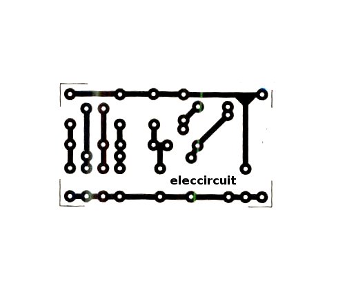
Figure 2 Single-sided PCB layout
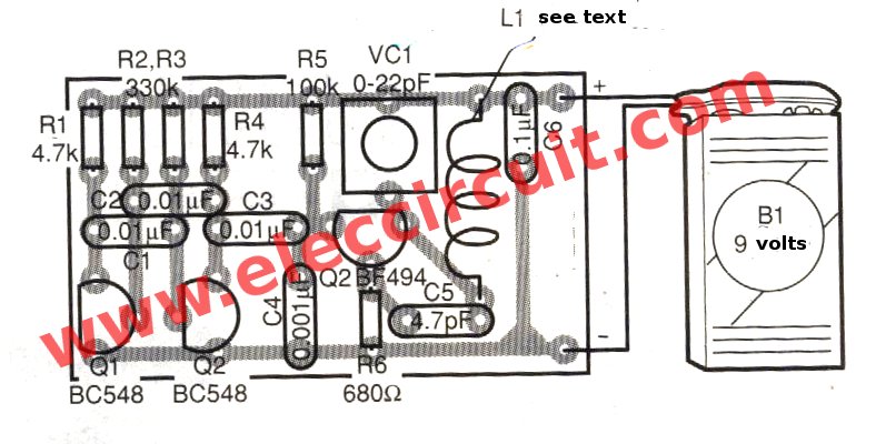
Figure 3 the components layout
In addition, If you do not want to do the PCB, can use the universal PCB form round hole. then solder pin of components to Connects.
Application
Do not forget that this pattern generator wirelessly. SoDo not need a the input cable connection the TV antenna.
But at the projects requires with the antenna. By using the plain wire length 30 cm. For use in the broadcast transmitters. Which radius of the audio signal of about 50M.
To tune the circuit to turn on the television in the VHF band. Tune until can receive signals from the pattern. Then use a plastic screwdriver to adjust VC1 until gets the image clarity and farthest.
This circuit very low consumption only 10 mA. The one 9 volts battery available long forgotten. So for a television repairman, this project have useful for you Certainly well worth the investment.
GET UPDATE VIA EMAIL
I always try to make Electronics Learning Easy.
Related Posts


I love electronics. I have been learning about them through creating simple electronic circuits or small projects. And now I am also having my children do the same. Nevertheless, I hope you found the experiences we shared on this site useful and fulfilling.
r6 looks 680 k in the diagram should be 680 ohm.
Thanks a lot.