My son wants to know more about MOSFET. I recommend trying to create a Long Duration Time Delay circuit. He said is easier than transistors can output power and good for switching and amplifier.
1. OFF After Delay circuit using MOSFET
2. ON After Delay using MOSFET
The Metal Oxide Semiconductor FET abbreviated as MOSFET. It is one of the most important transistors.
We use them in Microcomputer Memory to put a large number of MOSFETs on the Silver of Silicon.
Because MOSFETs are easy to make, they are small and eat a lot less. So new types of Power MOSFETs are very useful.
Normally, I will use the MOSFET as a good switch and amplify the sound very well.
The working of the MOSFET
I recommend the son to use the MOSFET-IRF540N number. Because of high performance, cheap, easy to use. It works like a transistor but has different legs.
The internal structure of N-MOSFET compared to NPN
And P-MOSFET compared to the PNP.
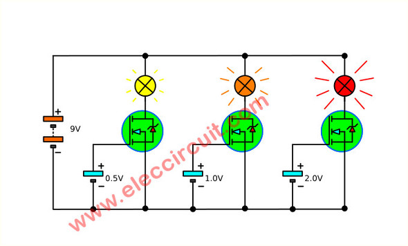
When the gate of MOSFET has a positive voltage, it will attract electrons to the region below the gate. The current flow the source and Drain to higher as the gate voltage.
Below, when use MOSFET to drive a lamp. We use less voltage to the gate, the lamp is much brighter if we use the gate voltage higher.
Also, we can use MOSFET is a simple liner dimmer.
Recommended: How does a SCR thyristor work?
Linear Light Dimmer circuit using Power MOSFET
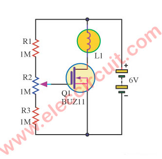
When we adjust the value of R2(variable resistor) down. A Lamp will dim, too. This circuit uses N-Channel Power MOSFET.
We connect R1, R2, and R3 in a voltage divider form. If the low voltage across the gate of MOSFET. It causes it runs less. And the current flows to load is lower, too.
Is it easy? Yes, you can use load is a lamp or coil. If you use a 6V power supply. You can use light bulbs of 4V to 6V.
Anyway, back to learn to continue:
OFF After Delay circuit using MOSFET
We press S2 (push bottom switch) to Close. The current will flow to charge in C1, Now it voltage drop across the Gate is voltage battery (9V). It makes the MOSFET works, the current flow pass through Source to Drain of MOSFET, the buzzer it will active sound.
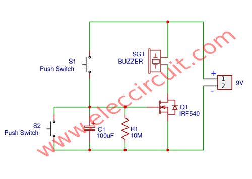
Then we release S1(OPEN) The buzzer will active sound. After C1 discharges internally or through R1 (optional), Q1 turns off and silences the buzzer. The long Time delay possible control by C1 and R1, 100uF for an hour.
If the time is very long but we need to stop ahead of time. We put S2 to reset or short circuit the current in C1 is Zero the same first.
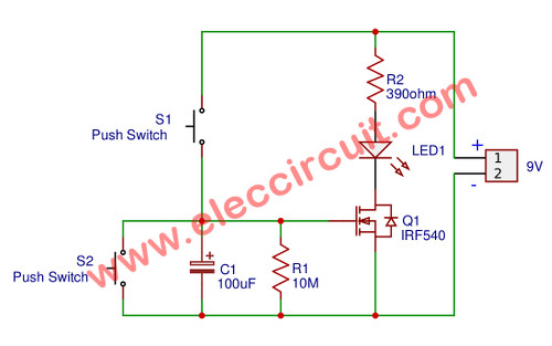
NOTE: The Load we use Piezobuzzer (or portable radio, Light, LED, etc.). Do not exceed the power rating of Q1. Use the R2 series resistor to reduce the current through Q1 and the load. Below we test it using LED as load.
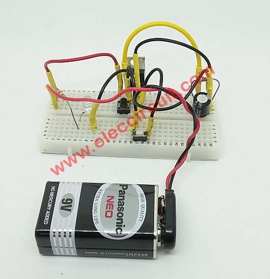
How to test it
My son tests this circuit on a breadboard, it worked.
Parts will you need
Q1: IRF540N, TO-220 MOSFET N-Channel 33A 100V
C1: 100µF 25V, Electrolytic Capacitors
R1: 10M, 1/4W Resistors tolerance: 5%
R2: 390 ohms, 1/4W Resistors tolerance: 5%
BZ1: Piezoelectric Transducer
LED1: LED as you want
Testing
1. Apply 9V battery to the circuit
2. Measure Voltage across C1 now is Zero
3. Press S1 voltage C1 is about 9V same battery
4. LED1 will light up
5. Time passes, Voltage C1 decreases gradually
6. When the voltage drops below 3V LED1, it will gradually dimmer. Until LED1 is completely extinguished.
7. During that, we press S2, it gives LED1 to go down as a reset.
On After Delay with MOSFET
This is ON After Delay circuit. Above We use MOSFET as in the circuit for Delay switch that easy more than the transistor.
Now, we add Q2 to inverts the status of Q1. Thus the buzzer sounds after the time delay is complete.
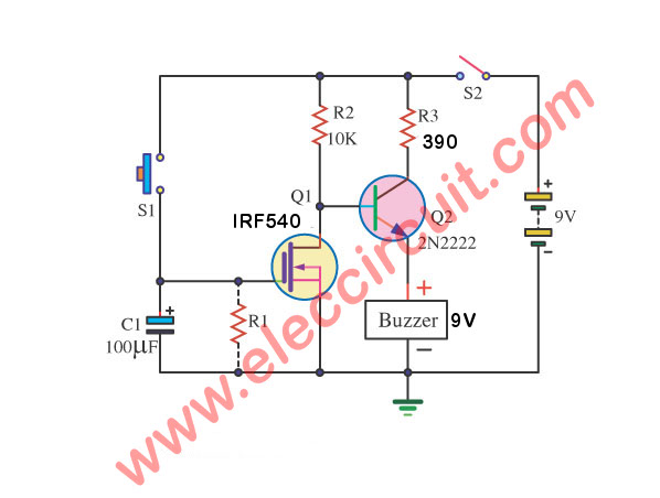
How it works
When we press S1(CLOSE), an electric bell will not loud suddenly, also above circuit now the C1’s voltage as hight so Q1 MOSFET active. The voltage across Drain -Source is zero.
The Q2 NPN transistor does not have bias current to Base so no current pass through Collector-Emitter. Thus electronics bell no sound.
Next, We released S1, but still no sound.
Over time, gradually. The MOSFET gradually less work. So voltage Drain-Source is higher.
It makes Q2 active,the base is biased to control the large current to Collector-Emitter to the buzzer sound up.
Note: The R2 resistors keep for decrease the popularity of an electric bell, R1 add keep for decrease the time down and decrease the noise give MOSFET. The Q2 use 2N2222 or BC549 or C1815 all NPN transistors
Parts will you need
Q1: IRF540N, TO-220 MOSFET N-Channel 33A 100V
Q2: 2N2222, 75V 0.6A TO-18 NPN transistor
C1: 100µF 25V, Electrolytic Capacitors
R1: 10M, 1/4W Resistors tolerance: 5%
R2: 390 ohms, 1/4W Resistors tolerance: 5%
BZ1: Piezoelectric Transducer
Not only that we also learn FET delay
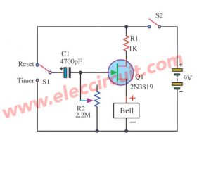
Basic Timer circuit using FET
This is the simple time delay circuits using JFET. Which it will alarm with a buzzer sound. In circuits have a few parts. And an important component is 2N3819-FET—Small-Signal N Channel Transistor.
Also, using the capacitor charge and discharged through resistors. Then, use voltage across them to control the gate of 2N3819 is ON. The buzzer will sound or the output is high for a long time as its capacitance.
It is ideal to learn a simple timers. You can do it in two-time delay circuits using JFET—VHF/UHF Amplifier N–Channel,
How it works
This electronic bell sounds output until the delay time for 1.5 minutes long.
First of all, Push a power switch (S2) on. Then, toggle switch S1 at the Reset position causes an electric bell or buzzer will loud.
If we toggle S1 come back at a set time an electric bell will silent, until time complete setting.
We will stop the electric bell at one time again. If friends change the value capacitor C1 or resistor R1 for delay long ago go up. And reduce R2 while stay in a position Reset for Reset fast go up.
We hope friends have fun the very simple alarm timer Basic Timer Circuit.
Parts you will need
Q1: 2N3819 JFET 2N3819-JFET Small Signal N Channel Transistor
BZ1: Electronic Bell or 3V Piezo-Buzzer
R1: 1K 0.25W Resistors
R2: 2.2M Potentiometer
C1: 4700uF 16V Electrolytic capacitor
S1: SPDT Slider Switch
9V power supply circuit
10 minutes FET delay Timer
This circuit uses the basic function of the 2N3819 JFET. Which acts as a switch. In the conduction and not conduction. It runs contrary to the transistor.
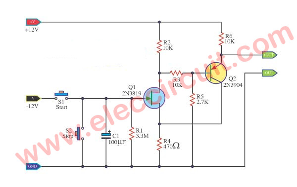
The circuit can be used to delay the cycle is small. Such as delay, 9-volt light bulb, or motor delay to any DC 9 volts. When raising the power supply circuit FET Q1 is running. D and S stand by the legs of furniture to the Tong Q1 will flow together, current flows through R2, so the flow from the legs through the leg and S. D, and through R4 to ground.
So no current flows into R3 to transistor Q2 does not conduct. Resulting in a voltage appearing at the output is 12 volt, but when I press the S1 switch current flows into the capacitor C1 fully.
Then go to the legs G of the FET. Q1 stopped working. Therefore, the current flowing through R2 is flowing to the R3 instead, and to bias transistor, Q2 to work on the output transistor Q2 is not working out for 10 minutes, because C1 is discharged.
The S2 is the reset switch. By acting shock C1 to discharge out soon. That the time delay depends on the C1. If it will delay much longer if less it will have less delay.
Parts you will need
Q1: 2N3819 JFET 2N3819-JFET Small Signal N Channel Transistor
Q2: 2N3906_40V 0.2A BJT PNP Transistor
BZ1: Electronic Bell or 3V Piezo-Buzzer
R1: 3.3M 0.25W Resistors
R2,R3,R6: 10K 0.25W Resistors
R4: 470 ohms 0.25W Resistors
R5: 2.7K 0.25W Resistors
C1: 100uF 16V Electrolytic capacitor
S1: normally open pushbutton switch
Simple Switch off delay circuit using 2N4871
This circuit prevents surges. When open switch off or power failure. The damage to electrical appliances. The circuit will switch to use a short period before the Power raising circuit to go.
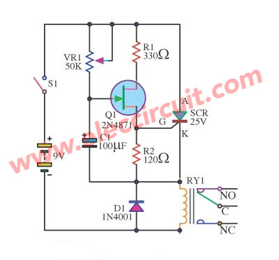
When raising the power supply 9-volt circuit then. Circuit delay. The duration of charging C1. VR1 is adjusted with time.
When C1 is fully charged, it will be pressure to bias the pin G of the FET 2N4891. Q1 to conduct work to trigger to pin G of the SCR to run.
Next, SCR relay will work to cut the flow circuit to work. If you want to delay it longer add the C1.

I love electronics. I have been learning about them through creating simple electronic circuits or small projects. And now I am also having my children do the same. Nevertheless, I hope you found the experiences we shared on this site useful and fulfilling.
#On After Delay with MOSFET
I want adjustable 1sec to 55sec on delay timer circuit pls help me anyone
#On After Delay with Mosfet
what kind of switch is the “S2″ in AFTER DELAY with MOSFET circuit” ??
#On After Delay with Mosfet
Hi @syed.s
Thanks for interesting this circuit.
I do not Wally the design. But would like to comment that You might try changing C100uF and R1.
I hope this comment still help you.
Good luck.
#On After Delay with Mosfet
Hi @aj.
S2 is normal on-off switch.
Thank for your comment.
#On After Delay with Mosfet
another question.. what value of your R1 in the diagram??
#On After Delay with MOSFET
I have already tested this circuit using BUZZER or LED as a load.. but it seems that it does not have any delay or the ascending sound of the buzzer.. is it okay if i use 12v source?? please do answer it as soon as possible sir..
THANK yOU.. GOD bless
Can you send the picture of the mounted circuit from top please?
he its very helpful blog please keepit
#Off after delay
Do we really need to use the piezoelectric transducer?