There are many radio Frequency circuit diagram that I collect them. They may be useful for you. The ideas are important for the learning circuit. I am sorry that cannot confirm it works and does not know the source. If you do not like it please tell me.
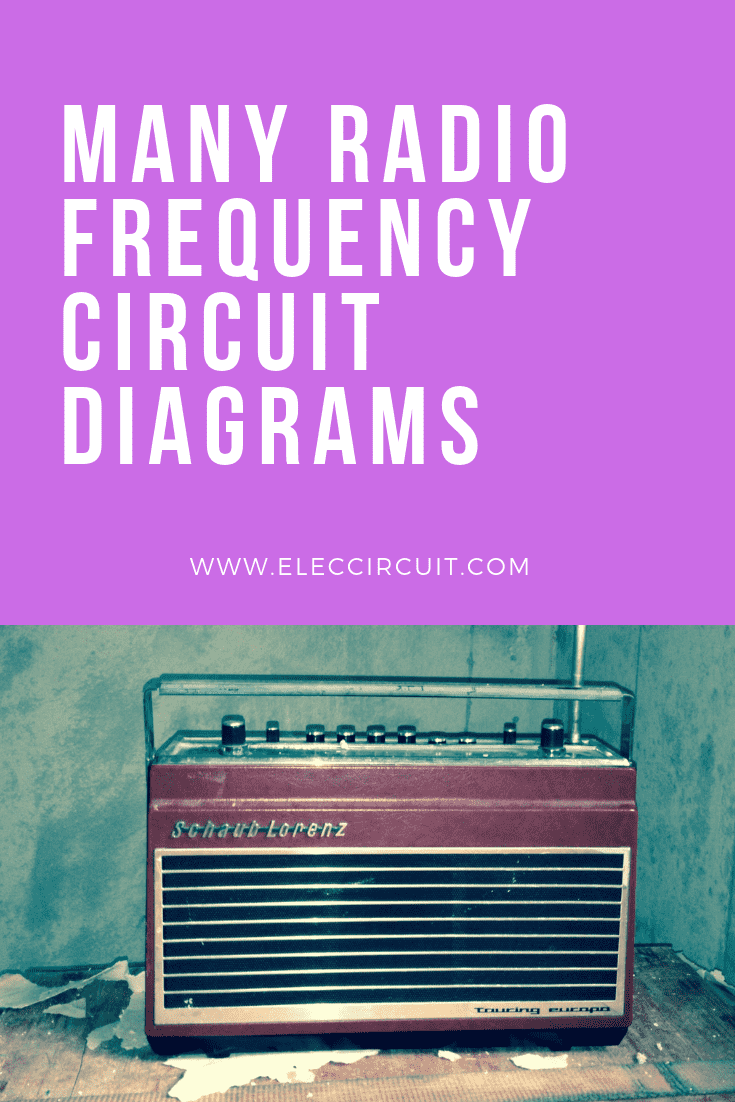
Simple field strength meter
This circuit is a Simple field strength meter that chooses a specific frequency range.
It can be used from 2 meters to 160 meters.
The telescoping antenna may be adjusted to its shortest length when working at 2 meters to keep the needle on the scale.
The meter should be a 100 microamp to a 500 microamp movement. The diodes are germanium type, such as 1N34, 1N60, etc. Silicon diode will also work, but they are a bit less sensitive.
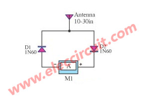
VHF Dip Meter circuit
This is a simple VHF dip meter circuit.The DIP meter is the frequency meter by use the LC resonance circuit that adjustable until the frequency show peak amplitude. The circuit include variable frequency generator circuit, rectifier and a moving coil meter.
In the oscillator include two transistors T1 and T2. The tuning circuit include C1 and coil Lx this coil will is outside the metal box.
When apply the power to circuit, the voltage from the oscillator will be rectifier by diodes D1 and capacitor C2. Then, send signal to P1 that use to adjust meter.
If bring the coil Lx near the others LC circuits, that resonance same the frequency is generated. This LC circuit will pull power from Lx, cause the lower voltage drop across the meter.
The adjusting frequency by C1 if the frequency resonance can read frequency by the meter.
The coil made of copper wire No. 19 SWG or 1mm. Wrapped 2 times on the core diameter 15 mm. The frequency range 50-150 MHz.
This transistors No. BF494 can operate at frequencies up to 150MHz. If needed, use the higher frequencies to change the number BRF91.
Which operate at frequencies up to 250 MHz. The capacitor C1 is 50 pF may be made of the mica capacitor value 100 pF 2 pcs in series.
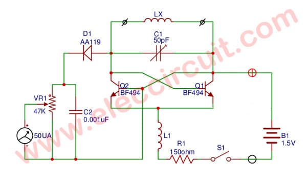
LED FM Tuning Indicator
Usually already the circuit F.M. Discriminator the majority will give an output that can modify tall and lower 0V depend on something tuning and often use drive Tuning meter at having junction universal position.
This circuit designs by use LED 3 pcs. Replace which regard as suit very with the usability. By when institute off-tune output of Discriminator change go to tall more or lower 0V make LED1 or LED3 shine respectively.
When the output of Discriminator equal to 0V LED2 stick for informing that something tuning best effective both of transistor Q1 with Q3 that use circuit model silicon PNP small signal the multi-purpose and Q2 with Q4 be model silicon NPN small signal the multi-purpose.
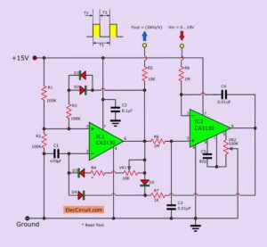
Depth frequency multiplier
Most of the frequency multiplier circuit using IC phase locked loop (PLL).It will increase the frequency to an integer only. But this circuit can double the frequency, in the integer to a fractional number. This circuit has an IC phase locked loop number NE565.
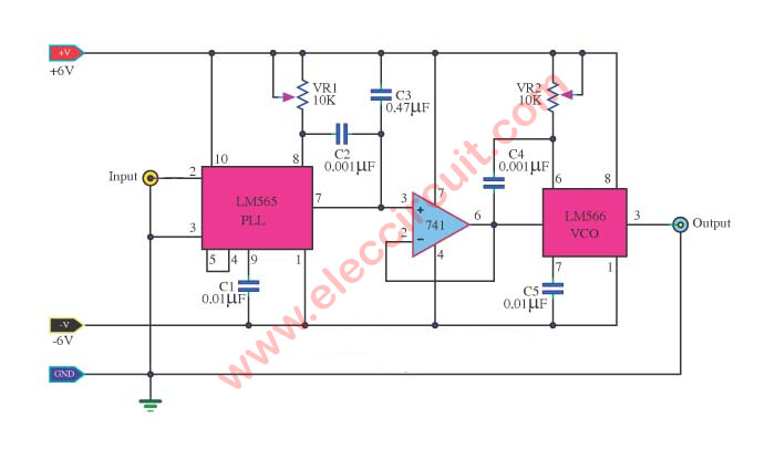
Circuit diagram of A frequency multiplier in depth
It changes frequency as the incoming voltage, Frequency control. That, from the IC Oscillator NE566. IC phase locked loop circuit is in the nature of Demodulator.
The output at Pin 7 and is connected to the IC op-amp 741. Which it connects in a manner of Voltage-follower circuit. To the driver IC 566 runs.
The voltage passing through the pin 6 of IC op amp, will be entered into a 5-pin of the IC 566.To control the frequency of leg 3 of the IC NE566.
The multiplication of frequency equal to R1, C1, R2, C2. For the operation of the circuit stability. Thus the value of R1 and C1 should be chosen to suit the frequency.
The input entered. Boost up the value frequency is selected by the value of R2 and C2.
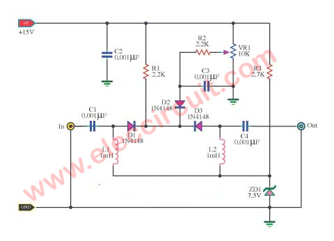
Attenuate variable radio frequency
The circuit designer it to attenuate signal frequency. We can adjust the amplitude from 1 to 40 dB.
If you want to use the band UHF. We should filter it within the flame shield. And C1 to C3 type feeds true.
The line should be short as possible, and the diode is a kind of low capacity at a high-speed frequency.
The potentiometer can be installed separately, if desired, as well as R3 and Zener diode.
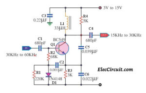
Background music decoder
This is a background music (SCA) decoder circuit from the input demodulated (multiplex) FM signal.
We use NE565 (Phase Locked Loop IC) to be base of this circuit, for easy and cheap.
A resistive voltage divider is used to set a bias for the input (pins 2 and 3).
The input passes through a two-stage high-pass filter, both to effect capacitive coupling and to attenuate the strong signal of the regular channel.
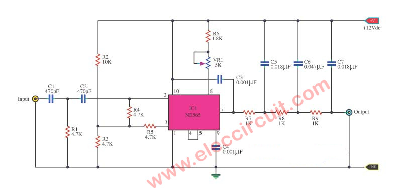
In all signal amplitude, between 80 to 300mV, is a need at the input, and should have an impedance of fewer than 10,000 ohms.
The Phase Locked is turned to 67khz with a 5000Ω potentiometer; only approximate tuning is required since the loop will find the signal.
The output passes through a three-stage low-pass filter to supply not importance and reduce the high-frequency noise which often joint SCA transmission.
And the output signal is in the order of 50mV and the frequency response offer to 7kHZ.
Ham radio transceiver RF indicator circuit
This is a Ham radio transceiver RF indicator circuit. It is small and easy to build.
The application a Ham radio transceiver has 3 characteristic differentials are
Firstly is Monitored status or Sometimes called standby, Means to turn on the Ham radio transceiver to To listen or wait for a call from either one, will have signal in the Input signal or not.
Secondly is a status that signal came in turn on may called Receive signal (Rx)
Thirdly is a transmit signal status called Transmit (Tx)
How it works
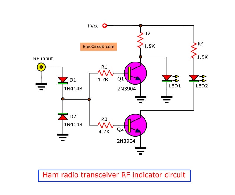
In circuit Figure 1 operation as standby status display indicator circuit or send only. By when connect at antenna line out of the ham radio transceiver to RF Input.
Figure 1 The Ham radio transceiver status display indicator
In normally status, when we do not push a RTT button (Push to Talk)To send signals D1, D2 no signal through Q1 and Q2, will also be OFF still, LED1 will glow because has positive current through R2 to LED to ground full circuit. The LED2 also go out because connected through Q2 which be OFF so not current flow.
When press a RTT button to send RF signal, then D1 will detect positive signal only. and D2 detect only negative that out of DCV, The negative signal will pass D2 to ground.
But the positive signal range in to drive Q1 and Q2 conduct pin C and E of Q1 Similarly, short-circuit it. Cause voltage between both lead is 0V, LED1 across has voltage drop across as 0V so go out.
The Q2 when ON will drive to LED2 glow up. And when release press key RTT will come back to new the standby status is LED1 glow. But LED2 go out.
How to build it
You do not make a PCB because this circuit is easy and small. So can put all parts into the universal PCB board as Figure 2
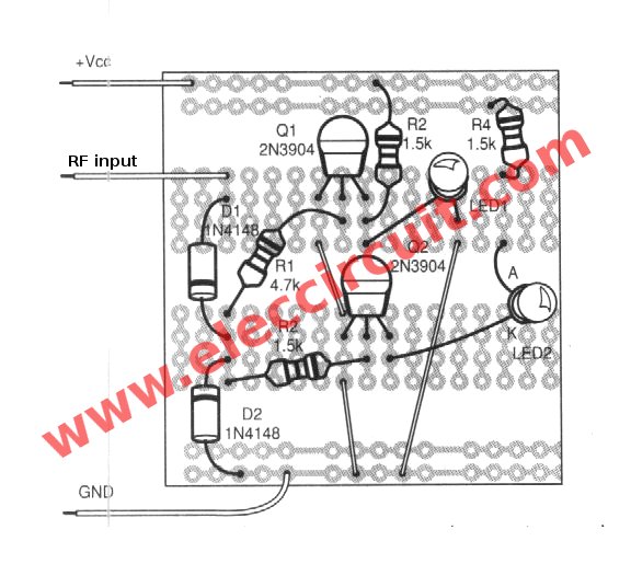
Figure 2 the component layout of this project
The components List
Resistors ¼W +5%
R1, R3: 4.7K
R2, R4: 1.5K
Semiconductor
LED1, LED2
D1, D2: 75V 150mA Diodes, 1N4148
Q1, Q2: 45V 100mA NPN Transistor, 2N3904
GET UPDATE VIA EMAIL
I always try to make Electronics Learning Easy.
I love electronic circuit. I will collect a lot circuit electronic for teach my son and are useful for everyone.

#VHF Dip Meter circuit
Questions/comments:
1. C1 (50pF) can NOT be two 100pF mica capacitors in series. The schematic shows this component to be a VARIABLE capacitor so the tank (oscillator Lx and C1) can be adjusted to the frequency of the nearby LC oscillator. When the needle on the meter drops, the Lx/C1 frequency is adjusted correctly. You then bring this oscillator circuit to a frequency counter to read the frequency. The meter dip only tells you when you are at the nearest proper frequency.
2. Are the instructions for the “coil” for Lx? If so, what is the specifications for L1?
#Depth frequency multiplier
I am not getting the required output in the simulation for the above frequency multiplier circuit
Super