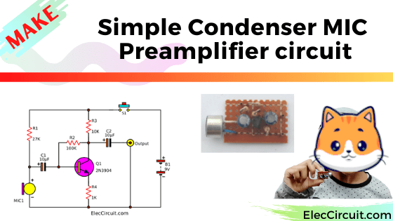
Today let’s try to make a microphone. By using a condenser mic preamp circuit. Why would we need said circuit?
Because of its high sound sensitivity, easy to use, small, and cheap. For example, It can be connected directly to your power amplifier through the AUX channel. Then, you could hear your voice clearly from the speakers.
I hope you will apply this circuit to a wide variety of applications.
What is an Electret Condenser Microphone
It is a type of electrostatic capacitor-based microphone. whose audio pickup section has a structure of a condenser consisting of a diaphragm and a back-plate opposite thereto, is called a condenser microphone.
The motion of the diaphragm by sound is picked up as a variation of capacitance between the diaphragm and the back plate.
In this case, usually, a voltage of tens or hundreds of volts should be applied externally as a condenser polarizing voltage.
However, electric charge can be maintained in a polymer film by the electret effect, thereby eliminating the polarizing direct-current high voltage. Such is an electret condenser microphone.
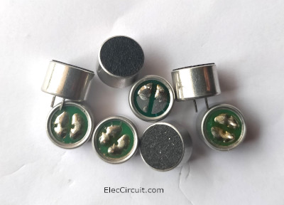
Almost all circuits involved in receiving audio this kind of microphone is often used for example mobile phones, intercoms, voice control switches, etc. because it is very sensitive, small size, easy to use and cheap, good sound quality. Suitable for medium and high-frequency sound.
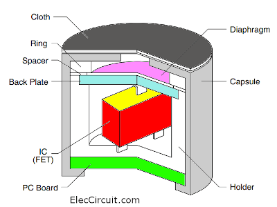
Look at a structural schematic of the Electret Condenser Microphone. There are diaphragm and back-plate to receive external audio signal and FET inside to amplify the signal and have a very high sensitivity. therefore responding to sound frequencies almost throughout the sound frequency range.
Look at a typical basic electret microphone preamp circuit. The two-terminal electret capsule contains FET a common source configuration. It must be externally powered by supply voltage V+.
The R1-resistor sets the gain and output impedance. The audio signal appears at the output, after a DC-blocking C1-capacitor.
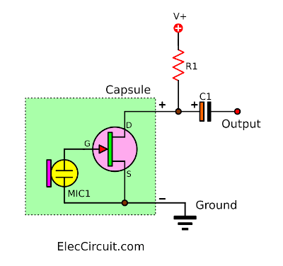
Therefore, If we connect it to the wrong polarity and no power supply voltage. It does not work at all.
Electret microphone on Wikipedia
How the Mic Preamp circuit works
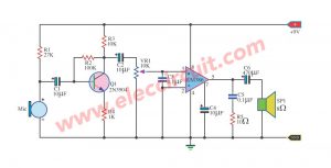
Look at the circuit diagram below. It has very few components.
First of all, we connect a 9V battery to the circuit. Secondly, a resistor R1 passes an electrical current to bias the Microphone (MIC1).
Also, R1 is a current limiting resistor for MIC1. It is ready to work. When we make a sound to MIC1, it causes the electrical signals to change.
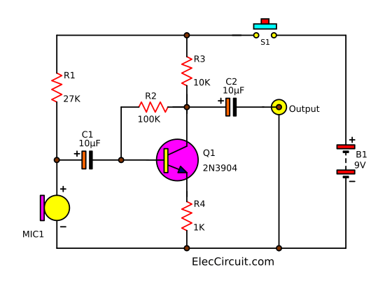
Then, the sound signal flows through a coupling capacitor-C1. It will block DC current not passing. But the signal is very weak. Therefore, it needs help with a transistor Q1 to increase the signal.
Next, the signal goes to B of Q1 to allow a larger signal from C to the output.
After that, the coupling capacitor C2 passes the AC signal to the output, a tone control preamplifier.
Also, you can connect the output with a headset to convert an electrical signal into sound.
The function of many resistors
- The R1 is a current limiting resistor for MIC1.
- Resistor R2 is a biased feedback signal from output to input by connecting between B and C of the transistor Q1. To provide stability for the good work.
- Both R3 and R4 act as to keep a bias voltage level to be suitable.
Learn: How to use LM386 audio amplifier circuit
Component list
Q1: 2N3904, 40V 0.2A NPN transistor
Electrolytic Capacitors
C1, C2: 10µF 25V
0.25W Resistors, tolerance: 5%
R1: 27K
R2: 100K
R3: 10K
R4: 1K
B1: 9-volt batteries, with Snap connector Or 9V power supply circuit
MIC1: Electret condenser microphone
Perforated PC board
Learn: Designing small signal amplifier circuit using transistor simply
How to apply it
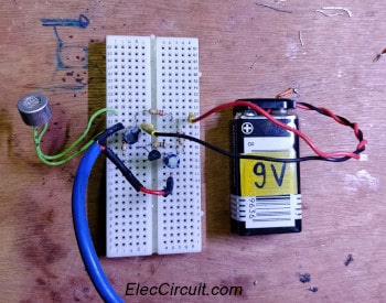
We try to assemble the above circuit on the breadboard.
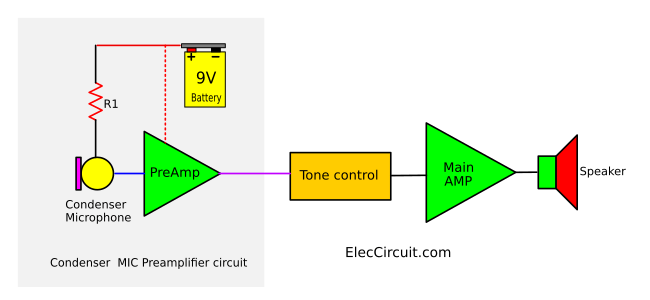
If you are a beginner, here is Connecting a Condenser Microphone Preamp with an amplifier system. Look at below, You should have a tone control preamplifier. Because the output of this mic preamp circuit has a weak signal.
Noise reduction
Nobody likes noise. I experimented with 3 different power supplies with this circuit.
- 9-volts battery Best results! I didn’t hear any noise.
- 9V DC Regulated power supply. Little noise! If you don’t notice, you can hardly hear.
- 5V mobile charger/ USB port. It is a kind of switching mode power supply. As it operates, it generates a very high frequency pulse and having too many harmonics. which is one of the noises, definitely enter the preamplifier.
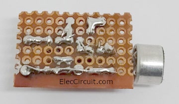
Assembling Condenser Preamplifier
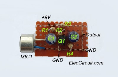
This circuit has a few components therefore we can assemble them on the universal PC Board or perforated board. Look at below, the components layout.
Step-by-step to build the circuit
Here is the specific method for building this circuit:
- Cut the small piece of perfboard out of a sheet. This PCB can be easily divided with the press forces of your thumbnail.
- Put components and carefully insert them through holes in the board, counting the holes to make sure everything is in the right place.
- Flip the board over and bend the wires from the components to anchor them to the board and create connections as shown.
- Make the joints with soldering iron.
- Trim the wires approximately with your wire cutters.
- Check each joint using a magnifying glass. If there is not enough solder, reheat it and add more. If the solder connection should not be there, use a knife to make two points away.
Note: This circuit only consumes about 0.75mA, so if we use a 9V 200mAh Ni-MH battery, be able for long around 266 hours (about one year).
This circuit uses transistors that are easy to build and cheap. If you want better performance, go for a high-quality Op-amp IC instead.
Download This
All full-size images and PDFs of this post are in this Ebook below. Please support me. 🙂


I love electronics. I have been learning about them through creating simple electronic circuits or small projects. And now I am also having my children do the same. Nevertheless, I hope you found the experiences we shared on this site useful and fulfilling.


does this work with other mics?if not why and what would change?
Hello John-Michael Holmes,
Thanks for your question.
This circuit is suitable for condenser mic only. And it is a simple circuit. It may be a low sound for you.
You may try this circuit: https://www.eleccircuit.com/dynamic-microphone-preamplifier-using-c945-transistor/
for Dynamic microphone.
I am sorry if I do not understand you. Because my English is not well.
Have a good day.
I am wanting to build my self an internal multiple mic accordion pickup
Would the circuit look the same if I needed to connect more mics up , eg. 4 mics into 1 output and then maybe even add a gain control knob ?
BTW Very good circuit explanations
Hello MH
Thanks for your feedback. You should probably try it with a mixer circuit. https://www.eleccircuit.com/simple-audio-mixer-circuit-with-fet-2n3819/
I’m not sure, will it work? for what you want. I haven’t seriously tried it. In the future, if I teach my children these circuits. We might try it again. Thanks for following up.
Hi,
I am using this mic:
https://www.akg.com/Microphones/Condenser%20Microphones/C411L.html
as a contact mic on the bell of a clarinet. (note: in the questions section, someone mentions “The C411L requires Plug-in-Power which is typically 2 – 6 volts, however AKG specs show the L model works on 2 – 12 volts.”).
I need to send the output to an arduino so I can check and display the frequency (a simple tuner). For the arduino to read the signal from the mic to determine frequency, it needs to be shifted 0-5V peak to peak (Voltage center on 2.5, not 0).
How can I send phantom power to this mic and amplify+shift the output signal so it is arduino ready?
Wow! In the eend I goot a weblog from where I can in fact tak uzeful dafa concrrning mmy study and knowledge.
Can this scheme use 12v voltage?
thank you for the reply ..
Hello,
Yes, you can use 12V power supply from AC adapter, or 12V battery.
Note: sometimes if you use low cheap switching power supply. It may have noise.
Thanks,