This is Analog signal selector switch. Do not waste time, choose the input method with interchangeable input cables. But press the input selector switch, as you like.
Easy and cost effective alternative is Input selection switch. With features the optional four-channel signal input. and volume to Increase or decrease the signal. In the event that your power amplifier no volume.
How This Circuit works
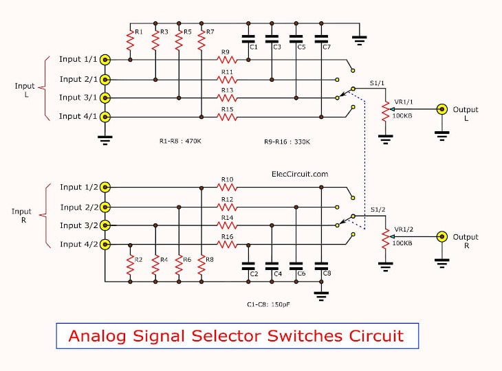
Figure 1 the analog signal selector switches circuits
From circuit in Figure 1 a selector switches(S1) will be selectness a input signal of 4 inputs, put it to work only one input channel. And three other channels of the remaining, S1 short circuit to ground immediately, Which there are R1-R16 and C1-C8 serve as directly the short circuit protection devices to the ground of signal input channel that is not being selected. To makes the CD player or various devices that bring the connection at J1-J8 input, not damaged by short-circuit of S1.
The signal input is selected will connect into VR1, which will be volume that adjustable the volume level of signal input before into J9-J10, As output is selected out off to the power amplifier or various devices.
How to builds.
Figure 2 show PCB layout Size of the prototype reality that we prepared before, and Figure 3 is a model of all components and the signal input panel selector switch. Which will see that has a few components. But must I have to be careful to solder the legs of S1. Because the copper line between the leg switches. Should be careful not to shock the pin of switches or, short to ground.
Application

Figure 2 The PCB layout

Figure 3 The components layout of the Analog signal selector switches
When the need will hear the sound from the source, press the selector switches on the location. We will see that this project is built. However, given the convenience, quick, cost really.
The components of List
Resistors ¼ watts + 5%
R1-R8: 470K
R9-R16: 330 ohms
Potentiometers
VR1: 100K
Polyester capacitors
C1-C8: 150pF 50V
Other devices.
S1: Push selector switch is 4 set.
J1-J8: RCA female jack to PCB 2 channel.
PCB 1 pcs. volume knob.
GET UPDATE VIA EMAIL
I always try to make Electronics Learning Easy.

I love electronics. I have been learning about them through creating simple electronic circuits or small projects. And now I am also having my children do the same. Nevertheless, I hope you found the experiences we shared on this site useful and fulfilling.
Could “www.electriccircuit.com” tell me if I can purchase the “Analog signal selector switches” above instead of having to build it?
if so , do you take American express?
good afternoon “eleccircuit.com” could you tell me there is no input power needed for this “circuit analog signal selector switches”?
thank you!
I d like yo gracias this información.
Hello Leonel García,
Thanks for your feedback.
Hello elleccircuit.com
Could you tell me if I need some power for this circuit?
Hello Jan Košťál,
Thanks for your visit. I like your question.
This circuit does not require any power supply.
Thanks
Apichet