This is simple electronic fuse circuit. It can be used to replace conventional fuses. Because it’s comfortable not need to replace the fuse every time the power too over. This circuit use transistors so simple and low cost.
The Fuse is a type of electrical equipment to the poor. Because it sacrifices itself. To protect the safety devices in the circuit. In the case of current flow in circuit too much. Until it melted. Due to an error in the circuit.
Fuse sold in the market. Can be used once. The structure is a glass cylinder with an alloy of lead wire is connected between the two terminals. When the current through it too much, Alloy within is temperature rises until the melting.Makes wires were cut off.
Sometimes the fuse works slowly. The below simple circuit may help you.
How to make super fast fuse using SCR
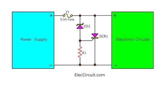
Here is how to make a super fast fuse using SCR. Why should do that? Sometimes fuse works slowly. It does not blow in a short time. So the circuit may damage. This is how help fuse works so fast. With two components, SCR, and Zener. Your circuit will be safe!
How does it works
Fuse is basic protection or electrical safety devices. Although it is very ancient, fuse still has many uses. It is easiest and cheapest than all devices. The fuse must blow when too much the current flows through it to protect the electrical circuits.
But if it takes too long. It may be too late. Our devices and circuits may be damaged.
Placing the SCR in the circuit, makes the fuse blow faster. When the voltage more than VZ of Zener diode. It makes the current can flow the Zener diode though gate of SCR.
After that, SCR works. It will pass many currents to the fuse very fast.
Last, Fuse blows immediately. It causes the power supply and loads safe.
For example, if you use a load 5V (digital circuits). You should use the Zener diode, 5.6V 0.5W.
What is more?
In some experiments, electronic circuits require fuse protection. The circuit may be difficult. Because, often short, to change the fuse every time. , Thus wasting time.
To solve this problem, we Build this electronic fuse limiter circuit, so instead of plain fuses.
By it can cut off the current immediately. When a short circuit as well. But can work immediately. Just press the reset button only. Convenient and economical than using plain fuses.
We also can set up and cut off current as you want.
If you are a beginner learn first: How does a SCR thyristor work?
Electronic fuse limiter works
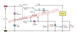
The electronic fuse that we use in this project is in Figure 1. Which will include important devices are transistors of 2 pcs, and Electronic devices in thyristors type of 1 piece works, together.
In Figure 1, This project across between the power supply and load that will be applied immediately, When an input of electronic fuse to the power supply. Then, Q1-transistor conduct current causes a Q2-Darlington transistor works as well, collector and emitter will conduct current by resistor R3 out to the Load that connected with the pin output(K2).
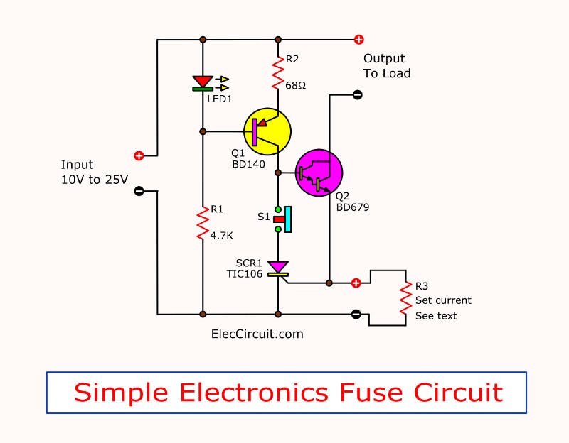
Figure 1 Simple electronic fuse
When the load use current will cause has a voltage across R3. If load use high current will cause the voltage across R3 too much as well. As Ohm’s law. And When Load use current until the voltage across R3 more than 0.6 volts. Then, this voltage will trigger to SCR1 conduct current.
This SCR or silicon controlled rectifier will works or conduct when get trigger at pin gate (G), and It will bring current indefinitely.
Although no trigger it.
How to stop the Works is remove its power supply there. We will bring this feature to use in our circuit. When voltage across R3 over 0.6 volts, the SCR1 will conduct , makes voltage at base of Q2 drop to level that transistor can not conduct high current.
From the original. collector and emitter has conduct current into stop, causes current flow to load next step, until push reset switch-S1 ,to separate SCR1 out of circuit. After that Q2 will start conduct current again.
In the section of Q1, LED1 and R2 there, will be together serving as a constant current circuit. To Q2 conduct when Normal conditions, and stop current to Q2, when SCR1 conduct current to ground.
Determination current of fuse
The current of fuse that you want to cut off circuits, can easily set easily from changing R3 which is a current detector. When we use Ohm’s law, which circuit will cut current when voltage drop across R3 is 0.6 volts.
Based this condition, we can find the right resistor with the following formula.
R3 = 0.6 ….(1)
I
We set I is the current that want to start cutting circuit. (Is measured in amps.)
For example want to start cutting at 500 mA wil must connet R3 are :
R3 = 0.6/0.5
= 1.2 ohms.
Thus, If you need the electronic fuse cut current at 500 mA, it must use R3 of 1.2 ohms. The rate watt resistant of resistor values (P) from:
P = 0.6x current value (amperes) ….(2)
Will have P = 0.6×0.5.
= 0.3 watts
So must select the Resistor of 1.2 ohms , the power rate is 0.3 watts But resistor size 0.3 watts no selling, so use 0.5 watts instead.
From example can easily define current of electronic fuse. Who Those who want to use fust in others currents,can It can be calculated from equation (1) and (2) to calculate Resistance (R3).
But should be less than 1 Amperes, because that Darlington transistor unbearable. And should be used only in the voltage of 10-25 volts.
How to builds
This project, with a small number of devices are easily constructed. Start from build PCB lay by size in figure 2. And place the device in the form in figure 3. It needs to be careful because the transistor leg and SCR similar shape.
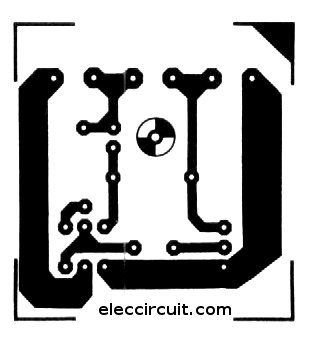
Figure 2 The PCB layout of electronic Fuse
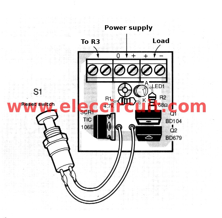
Figure 3 The components layout
The components List
Resistors ¼ W + 5%
R1: 4.7K
R2: 68 ohms
R3: see text
Semiconductors
Q1: BD140, 100V 1.5A PNP transistor
Q2: BD679, 100V 2A NPN transistor
LED1 (Light emitting Diode) Red 5 mm.
SCR1: TIC106E
Other parts.
K1-K3 terminal into PCB
S1 Switch, press the off, released stick.
etc.
GET UPDATE VIA EMAIL
I always try to make Electronics Learning Easy.
Related Posts


I love electronic circuit. I will collect a lot circuit electronic for teach my son and are useful for everyone.