Today we will be talking about the simple voltage level detector circuit. Its main purpose is to detect if the voltage rises above a certain point. Despite its simplicity, this circuit is an excellent way to learn about comparator circuits.
We will use the LM741 OP-AMP as the main component of this circuit. This chip is a very popular general-purpose operational amplifier IC.
Basic Comparator
A comparator is a circuit that compares two input voltages. One is referred to as the reference voltage, while the other is the input voltage. A comparator then compares Vref and Vin and outputs a digital signal accordingly.
Some integrated circuits (e.g., the LM339) are specifically designed to function as voltage comparators. Nonetheless, we are using an OP-AMP today, which has a very high open-loop gain, allowing it to function as a comparator with a feedback resistor. However, a general-purpose chip, such as the one we are using, may lack some of the features of a proper comparator.
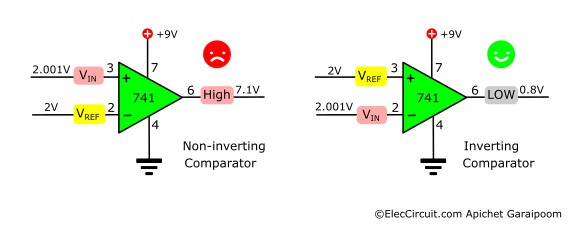
The illustrations below show the LM741 functioning as a comparator in its inverting and non-inverting operating mode.
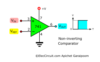
In non-inverting mode, when Vin exceeds Vref, the output switches from low to high.
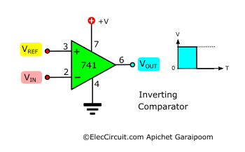
Whereas in inverting mode, when Vin exceeds Vref, the output switches from high to low.
Experimenting With A Simple Circuit
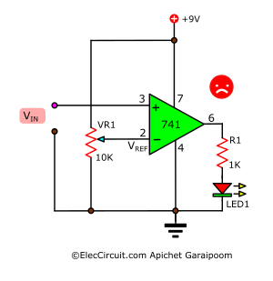
We built this simple comparator circuit on a breadboard to learn the basics of a comparator. VR1 and VR2 act as voltage dividers, providing a range of voltages to both of the LM741 inputs. Q1 turns on the LED when the LM741 outputs a high state.
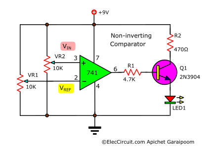
Assume VR1 is set to its center position to give Vref = 4.5V (9V ÷ 2 = 4.5V); VR2 controls the Vin. Our goal is for the LED1 to light up when Vin exceeds 4.5V.
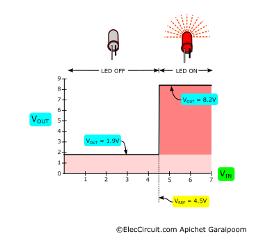
The graph above may help us understand it better. The Vout has two levels, 1.9V and 8.2V, which is analogous to “low” and “high” states in a digital circuit. In the “low” state, the LED turns off; whereas in the “high” state, the LED lights up.
Therefore, when Vin is within the range of 0V to 4.5V, the Vout would remain in the “low” state. However, the moment Vin goes up to the 4.5001V to 7V range, the Vout would switch to the “high” state.
Do note that the lowest output voltage level is not “zero” but 1.9V.
Simple Level Voltage Detector Circuit
Now let’s build the simple voltage detector circuit using what we learned above. Since we want our circuit to be small, we pick the 3mm red LED that only requires 1.7V at a current of 3mA. A benefit of using a small LED is that we do not need Q1 anymore; the LM741 alone could output enough current to drive the LED.
As for the input part, we kept it the same, in the sense that the reference voltage (Vref) is connected to the inverting input (pin 2) and the input voltage is connected to the non-inverting input (pin 3) of the LM741.
We expect that LED1 will light up only when the input voltage exceeds the reference voltage, which we set to 2V—however, the result is not that. LED1 lights up all the time, even when the input voltage is less than 2V.
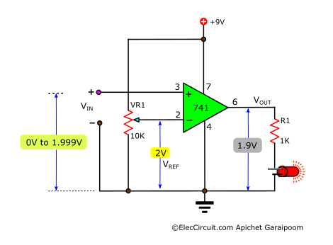
This is because we use a single power supply for our OP-AMP IC. Meaning that even in the “low” state, the output is not “zero” but 1.9V, which is still enough to drive the LED1.
Switches to Inverting Comparator
To solve this problem, we would need to think backward from the output. We see that switching the load (LED1) to the positive supply will result in a lower “low” state voltage.
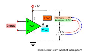
In this new load configuration, the “low” state voltage changes to 0.8V (9V – 8.2V), and the “high” state voltage changes to 7.1V (9V – 1.9V). However, this also means that the state of the output is reversed.
As a result, we would want LED1 to light up when the output is in the “low” state, which acts as a ground. This is why we need to change the LM741’s operating mode from non-inverting to inverting. When the Vref = 2V and the Vin = 2.001V, the output will be in the “low” state.
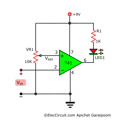
Finally, we have the simple level voltage detector circuit using the LM741, as shown below. VR1 determines the reference voltage. Vin should not exceed VCC or 9V.
Testing
As shown in the video below, we assembled the circuit onto a breadboard. To test whether it works, we want to set it up to detect when the voltage exceeds 2V. Here is the step-by-step process:
First, after applying 9V to the circuit, we adjust the VR1 potentiometer until its voltage reading is 2V, which will be the reference voltage (shown in the left multimeter). The LED remains off after the input voltage lower than 2V is applied to pin 2.
Then, I continuously increase the input voltage (shown in the right multimeter). When the voltage reaches 2V, the LED lights up, and the output voltage reads slightly lower than 9V.
Other circuits using 741 Level Voltage Detector
- Simple Temperature Sensor using a Diode
- Car Overheat Alarm Circuit
- Automatic OP-AMP Night Light Circuit
The event above simple circuit diagrams are old. But now they are still working. Of course, you can learn electronics from them.

Written by: Apichet Garaipoom
Like many others, I started electronics with curiosity and simple circuits. Over time, I’ve found joy in sharing what I’ve learned—and now, I get to build with my kids. It’s a journey, and I hope this site helps you enjoy yours.
Read more about me
Have a circuit that comes from the dash info center of my Dodge Diesel, it is the low fuel level reminder light driver. It appears to be an Op amp( 8 pin ) and a power transistor. Neither of these parts have #’s which I have been able to use to identify them with. The light will not go off no matter how much fuel is in tank. The circuit is no longer replaceable from the Dealer as it is too old a model. IC # is CB9047n — Transistor # is simply 6209 thought possibly this # might be a Vreg. The circuit has a lot of components just to be a driver such as a voltage to current converter which is what I surmise. There are only 4 connections to the board, so 1 has to be V+, 1 v-, 1 going to the light, and 1 coming from the gauge sending unit, which has 3 wires to it, +,- and the signal wire which is a variable voltage. If the parts can be identified, I would use a replacement of similar value and rebuild the board. If not I must make a new board that will do the same job, turn on the filament lamp when the signal from the sensor reaches a set V. and turn off when the V is out of low limit range. I have some ideas on how this should be done, but starting over from scratch will be more work then simply repairing the original circuit. Got any suggestions?
find that the op amp is a dual so it will not be difficult to replace this if the part does not a critical spec sheet,which I doubt it does. So it looks like I’ on the way to getting it figured out. Still welcome any info or suggestions.
Does this circuit only work on sensing a DC voltage or will it also work on an AC (audio) signal – for example to confirm that the amplitude is correct?
Yes, in theory, it can sense AC Audio signals with just a few adjustments to the circuit. But we have not tested it yet, so it might be a waste of your time or even a risk of circuit errors.
Anyway, this circuit is still interesting, maybe in the future, we (I & my daughter) will experiment with this circuit.
Please stay tuned.
This could be answer to what I need.
The cct you give runs on 9V ….. I need to use 12V, as a 741 will works up to 22V is the only change needed to get correct resistor value for R1 to suit LED
R = (Vs-Vf)/If
Hello, Rick Hughes
Thanks for feedback. The 741 chip is normal op-amp. You may try LF351 it is better one.
If you use it for detect voltage I think you may use LM339: https://www.eleccircuit.com/low-voltage-battery-indicator-circuit/
Thanks
exelente projeto para iniciar outros a partir deste. so usar criatividade. parabens