I have ever shown you an FM Wireless Microphone circuit. It is good to play with our kids. Or Learn RF transmitter circuit works. But, is the distance too short? Try this circuit. Add another one transistor in an RF amplifier. So, this has two resonance circuits, and also two trimmers. Cause Higher efficiency and more transmission far up.
Simple FM wireless transmitter circuit
Imagine you and friends are going to sing a song. All are happy.
But often the cable of the microphones tangle.
Is it better if no cable? Yes, this circuit can do. It is suitable for the beginner to learn the RF transmitter circuit, too.
Do not keep worried that it is difficult or expensive.
It is easy and cheaper than a normal high-quality microphone with cable.
Are you up for it?
How it works
Basic principle:
We speak to Microphone. The circuit will get this sound signal to mix with FM frequency to transmit the broadcast spectrum.
Then, we get the audio sound from FM radio receiver In the matching radio frequency channel only.
Real circuit working
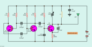
Look at a circuit diagram below. It is a small circuit. But is a good teacher for a transmitter circuit.
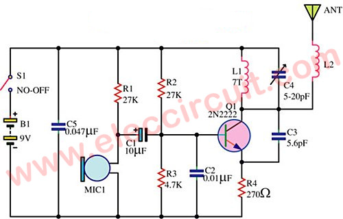
This is a step by step process:
First, we speak into a MIC1. It is special part called a condenser microphone.
Inside it has an amplifier module to amplify our voice. To be a higher level before sending it to the output leg.
For this reason, this MIC requires a little current to power them.
We will see the R1-resistor 27K pass voltage to a positive leg of a microphone.
At the same, this leg is its output, too.
Second, a C1 is a coupling capacitor. It passes only AC signal
to a base of Q1.
Which the Q1 acts as two things are.
- a radio frequency(RF) generator
- an audio mixer
To mix the sound signal and the RF together.
And, at base of Q1 has both resistor R2-27K and R3-4.7K. They are a divider circuit. To set a level voltage to bias current of Q1.
For capacitor C2-0.01uF connects to the ground to bypass the high frequency.
And, collector of the Q1 connects with positive voltage pass the coil.
For this coil, we use a copper wire No. 19-20 AWG, wrapped around the air core diameter of 7 mm.
You should wrap 7 rounds, similar to coil spring.
Then, stretching out to a length of 15 mm.
At close, this coil has a capacitor-C4, 5-20pF. It is the adjustable capacitor from 5pF to 20pF. We called timmer. It is connected to a frequency tuning
While the collector of Q1 connects to the antenna. Which in this circuit, we use an antenna that is built with yourself.
By using the copper wire 16-20 AWG, about 7 inches in length, and curled into a circle like a spring, about 6 mm in diameter.
The length of the wire coil to the end. Then take one end soldered to the antenna connection.
How to build
This project you may use universal PCB or look at PCB layout on image below.
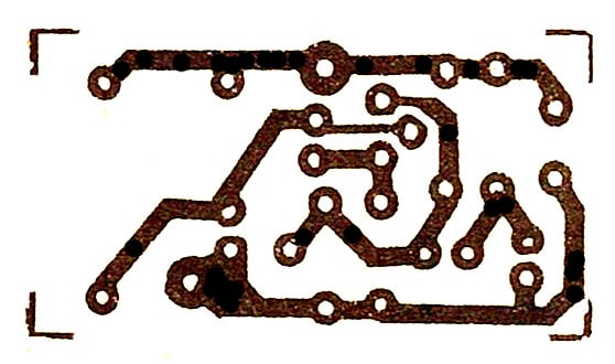
Figure 2: Copper PCB layout
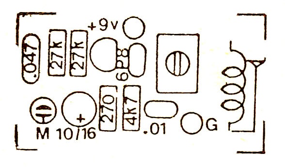
Figure 3: Components layout
Creating an electronic project often has similar steps.
You should install a small device first.
Connect a shielded cable length about 5 cm to connect a condenser and the PCB.
We use the coated copper wire for to prevent rust green from moisture in the air.
At the end of the wire should scrape out with a razor blade before solder.
Use a lead solder a better mix of 60/40, and requires some skill in soldering.
Otherwise, the spectrum not work. It is a high frequency.
How to tune
When completed. Check and Check again.
Let’s tune. Here are the steps:
Take the FM radio, open station radio dial in the middle.
Turn on the FM wireless transmitter circuit.
Use a screwdriver plastic or plastic sheet flat spin adjust the trimmer.
Speak into the microphone
Tune until it has the sound to the FM radio.
If tune the trimmer until full cycles, Not yet match wave. Try stretching or shrinking of the coil.
Then, adjust the new one. And try some stretching or shrinking the antenna, in order to deliver the best results.
If all the fine-tuning does still not work. Also, try turning the radio waves, may rotate to the minimum frequency and maximum frequency, or turn around the station.
Then try to adjust it again.
When adjusting until available.
Then, install the circuit into a plastic box or aluminum box.
Or any box ready to build up own. By folding a sheet of aluminum or a plastic sheet is glued to the box for convenience to you.
Note:
As a principle, this circuit sends far about 100 meters. It depends on:
- The location.
- Low or high noise oscillator.
- Low or high-quality component
- The soldering is good or not.
So, it is difficult to determine how far?
But from my experience, in the center of the floor to the two floors of the building.
It is enough for the small and cheap circuit like this.
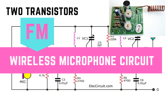
Two Transistors Wireless Microphone Circuit
Technical information.
- Use DC Power supply of 9V
- Maximum consumption current about 10mA
- Transmission frequencies in the 88 MHz.
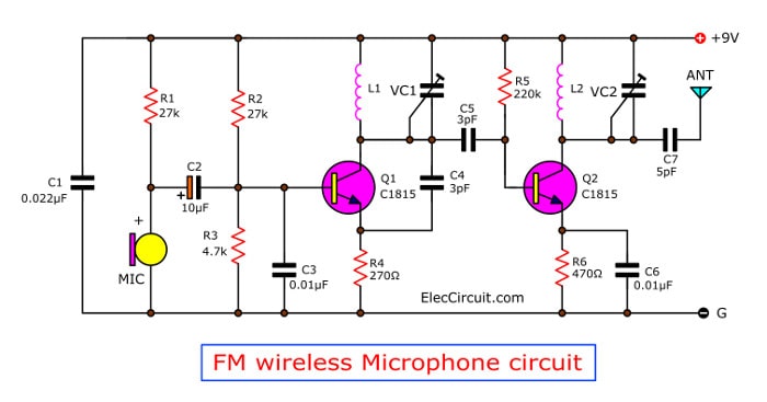
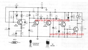
Figure 1 Two transistors FM wireless microphone circuit
Look at Figure 1:
A MIC1-condenser microphone is an audio receiver. It converts our voice to an audio signal.
Then, the signal flows C2 is a coupling capacitor into the base of Q1-transistor.
Which this transistor and a few parts around itself, have 2 functions.
First, generate high-frequency oscillators.
Second, mix audio signal into radio frequency (RF).
Then, the RF signal comes to the base of Q2 through the coupling capacitor-C5. The Q2 amplifies the RF goes out of a collector.
Then, send out to an antenna.
At collector lead of Q1 and Q2 have copper wires. They are working as a general coil.
How to builds its.
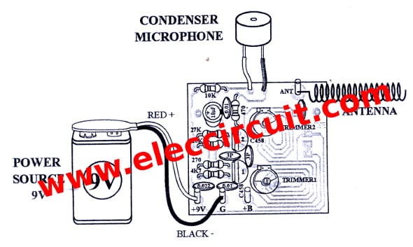
As Figure 2, the components layout and wiring of this project.
I am so sorry for cannot show PCB layout for you.
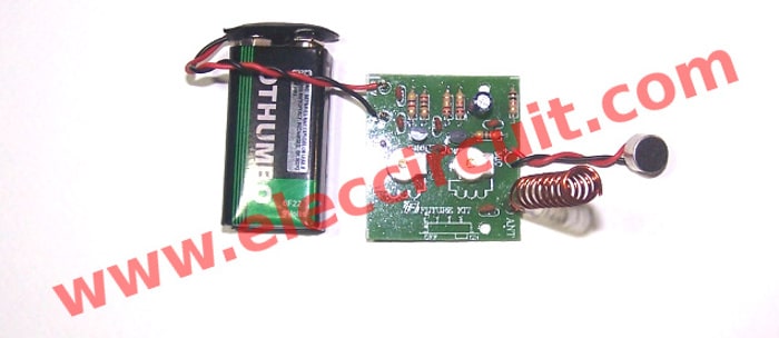
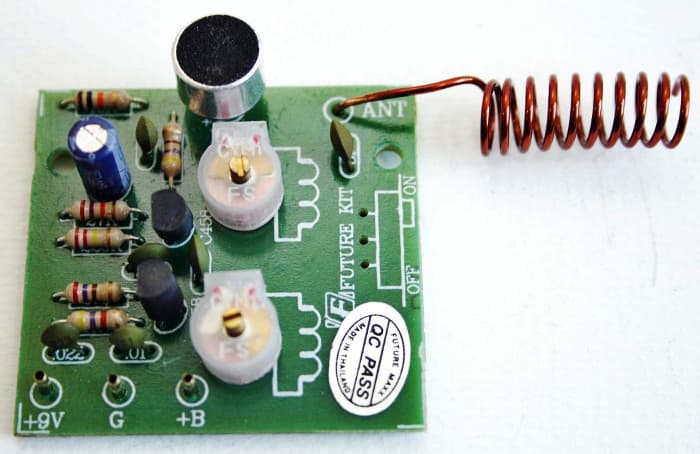
Then Figure 3, the complete FM wireless microphone circuit on PCB.
Testing the FM wireless microphone
First, apply the 9 volts battery to the positive terminal (+9V) and negative (G terminal).
Second, for ANT point connects to the coil.
You have to scrape off the enamel of copper coil. before soldering it.
Then, Set the FM radio stations to positions 88 MHz.
Next, use a plastic screwdriver to gently adjust the trimmer VC1, Until it whistles howling out the radio.
After that, try to speak into the microphone.
However, if no sound on speakers. You may try to turn the radio to about 100MHz.
If this is still no sound, you turn the radio all the way to 108MHz and try again.
Then, adjust Trimmer-VC2 in order to get more distance.
Also FM wireless transmitter
The components list
R1, R2: 27K
R3: 4.7K
R4: 270 ohms
R5: 220K
R6: 470 ohms
ELECTROLYTIC CAPACITOR
C2: 10uF
CERAMIC CAPACITORS
C1: 0.022uF (223)
C3, C6: 0.01uF(103)
C4, C5: 3pF
C7: 5pF
TRANSISTORS
Q1, Q2: 2SC458, 2SC828, 2SC945, 2SC1815
B1: 9-volt battery Or 9V power supply circuit
I am happy to see to save time. I found this project on Amazon
GET UPDATE VIA EMAIL
I always try to make Electronics Learning Easy.

I love electronics. I have been learning about them through creating simple electronic circuits or small projects. And now I am also having my children do the same. Nevertheless, I hope you found the experiences we shared on this site useful and fulfilling.
I HAVE MADE IT WITH R4 AS 100 OH.AND AT THE PLACE OF MIKE I PUT 470K AND A JACK,WITH ONLY 3V.SUPPLY,PLYING MP3,IT THROWS SIGNAL UP TO 25MTRS.
Is it possible to build a circuit which will have inputs from the tv or an ipod and then transmit to the receiver
can i plug in an audio source instead of using the mic and what part should i remove ? thnx
how do i compute the freq. guys?
thanks in adv.
I want a radio transmitter which can transmit long range area of 30km by 30km so how can i get it ?
to play mp3 , you can remove the microphone and feed the output of a mp3 player through a 10uF electrolyte capacitor.
how can i get the pcb for this project?
because the coils is printed on board
Hi,ami rosenberg
Thanks for your feedback.
I am sorry for not have PCB layout.
what distance it work?
please tell me
Hi may I know the value of the trimmer and the L1
Hi,All
I am sorry this is circuit Kit only.
so I can not show you trimmer and L1
can we have the list of the components needed to make the circuit diagram above, the wireless fm transmitter? thankyou. have a good day!
hi there!nice project.i wonder if this could be used for guitar to have a simple wieless guitar system?will i be modifying the circuit if this would be used as such?thanks in advance
so how many turns on L2?
Hi alex,
Please more in detail:
we use copper wire No. 19-20 AWG, wrapped around the air core diameter of 7 mm. You should be bind seven around , similar to coil spring, Then, stretching out to Length of 15 mm.
hey can you tell me what is the purpose of C3 in this whole circuit at [email protected] regards
hie, l just built the circuit and connected the dc source but its refusing to pick up signals, how best can l troubleshoot the problem?
which type of antenna is use here??
Sir I want mini project in which am,fm modulation, transmiter and reciver is used
hi I cannot know the value of the trimmer.
Hi brother i want to you help me. I need a circuit can talk together . Such as police radio.
Thank!
Mr.Ratha
A wireless HDMI video transmitter solves that problem, allowing you to send an AV signal wirelessly across the room or through walls to another location.
Thanks 🙂
Twirling both tuner is changing channel. How to select best twirl for most outside signature?