If you are looking for a comparator integrated circuit that works well at high frequency, is small-sized, and needs only 3.7V to function, the LM311 differential comparator OP-AMP is what you are looking for.
Even though this chip is ancient by today’s standards, it is still relatively popular, and we do use it regularly.
The LM311 is a type of operational amplifier (OP-AMP) similar to the LM339 but with the feature mentioned above. One of the enjoyable parts of electronics is picking the right component for the work we are doing.
So, let’s get to know the LM399’s datasheet, pinouts, features, and example circuits so that we know how to use it when the time comes.
LM311 Differential Voltage Comparator
The LM311 high-speed differential voltage comparator is used to compare voltage. This chip has been around for a very long time now. But what sets this chip in particular apart from other OP-AMPs is that it has an integrated transistor output, which means that the output can be isolated from the ground of the LM311.
It has a wide range of supply voltage as well as being compatible with most TTL, RTL, DTL, and MOS ICs. It is also quite fast; typically, the response time is less than 200ns.
Features
There are many interesting features about the LM311; here are some of them.
- Wide power supply range: 5V to 30V for single supply and ±2.5V to ±15V for dual supply.
- Can operate from a single 5V supply.
- Capable of driving loads up to 40V and 50mA.
- Can drive most TTL and MOS loads.
- Output can be Isolated from the circuit’s ground.
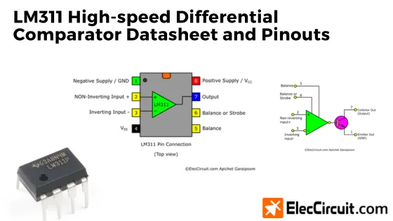
Pinouts and Internal Structure
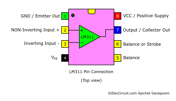
| Pin | Type | Pin Name | Pin Functions |
|---|---|---|---|
| 1 | OUT | EMIT OUT / Negative Supply (GND) | The emitter of the internal transistor; usually connects to the ground |
| 2 | IN | NON-Inverting Input (+) | The non-inverting input of the comparator |
| 3 | IN | Inverting Input (-) | The inverting input of the comparator |
| 4 | Power | Negative Supply / VEE | A negative supply connects to the ground |
| 5 | IN | Balance | Determines the balancing offset voltage |
| 6 | IN | Balance / Strobe | If connected to ”low,” the output will be off regardless of the voltage differential. |
| 7 | OUT | COL OUT | The collector of the internal transistor; treated as the main output |
| 8 | Power | Positive Supply / VCC | A positive supply connects to the power supply |
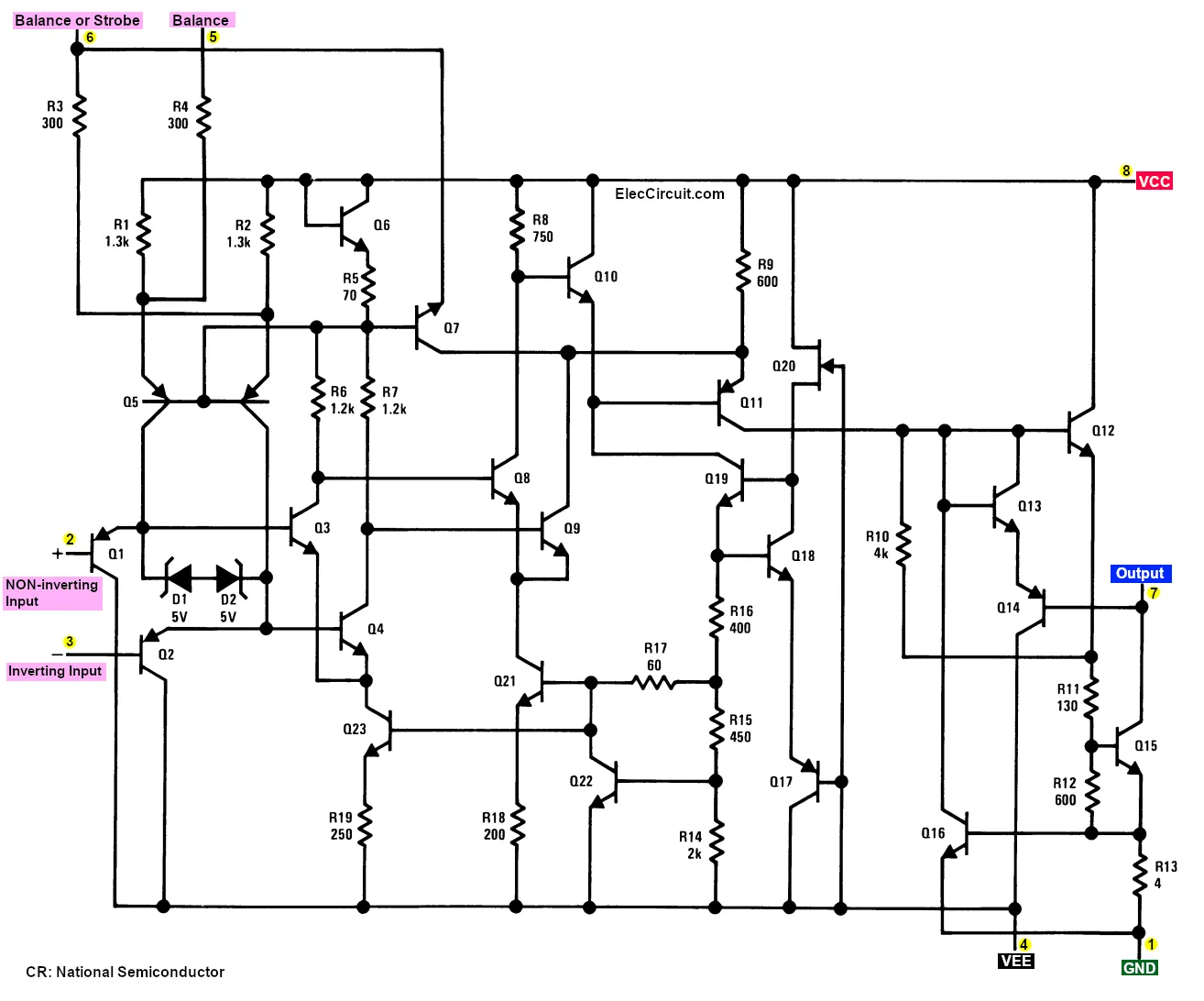
Internal Schematic Diagram
Inside the LM311 exist many components, as shown below.
After simplifying the LM311 internal components, we were left with this diagram below.
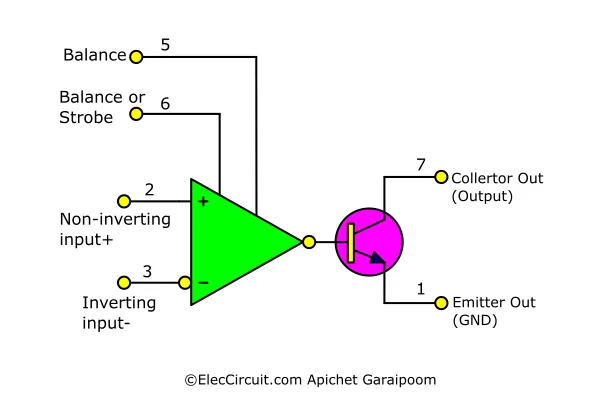
We can see that the output of the comparator is connected to an internal output transistor, which acts as a driver for the loads. This means that the loads can also be isolated from the comparator’s circuit.
Specifications and Practical Usages
The LM311 has a minimum supply voltage of 3.5V; from our experience, using a 3.7V battery is adequate. Furthermore, when using it with a TTL, the LM311 can share the same 5V power supply with the TTL chip. On the other end of the spectrum, using a supply voltage of 30V is possible since the LM311 has a maximum voltage rating of 36V. While on a dual power supply setup, the maximum supply voltage is ±18V; however, it is recommended to not exceed ±15V for safe and stable operation.
From our testing, the output current is about 5mA at the voltage of 3.7V, which is enough to drive a 3mm LED. However, this chip can drive outputs up to a current of 50mA, together with a maximum power dissipation of 500mW.
Anyhow, we recommend not pushing the LM311 to that degree; it will overheat and become unstable. It is better to only use this chip at 10mA or even lower, then use an amplifier circuit to increase its output down the line. Furthermore, do not forget to use a proper regulator power supply, as that will greatly increase stability and get rid of unwanted noise.
Even if the LM311 has short-circuit protection, we must be cautious not to connect it in reverse polarity. We should also not supply the chip with too much current because it may cause excessive heat and operation errors.
Here are some of the maximum ratings of the LM311.
- Maximum current from VCC: 7.5mA
- Maximum input current: 150nA
- Maximum offset current: 20nA
- Maximum total supply voltage: 36V
- Differential input voltage range: ±30V
- Power consumption: 135mW at ±15V, 500mW max
- Rated operating temperature from -40°C to 125°C
Applications
The LM311 is used in all kinds of applications; some of them are listed below.
- Voltage Comparator circuits
- Zero Crossing Detector
- Peak voltage Detector
- Comparator and Solenoid Driver
- High Voltage Protection/Warning
- Oscillator Circuits
- Low-voltage Adjustable Reference Supply
- Digital Transmission Isolator
- Precision Photodiode Comparator
- Switching Power Amplifiers
Equivalents for LM311
If the LM311 is unavailable, you could instead substitute it with a similar IC, such as LM111, LM211, LM710A, NTE922, and LT111A. Other equivalents are:
- LM339—it is a quad comparator IC, meaning that it contains four different comparators within it. It can be used in place of the LM311, just three more comparators come with it.
- LM324—it is another quad OP-AMP IC with a comparator function; however, it might not perform as well as the LM311 in that role. Nevertheless, in common usage, it can substitute for the LM311.
In summary, finding an equivalent for the LM311 depends a lot on your specific usage. The function of a comparator is one of the cornerstones of these OP-AMP ICs to begin with. It is just the details and specifications that are different between them.
Therefore, you may want to check with the manufacturer’s datasheet of a specific model if it is suitable for your workload.
LM311 Datasheets
Here are the datasheets for the LM311 chips from their manufacturers.
Example Circuit of LM311
Now that we know the basic technicalities of the LM311, let’s put them to good use by learning or building these example LM311 circuits.
Voltage Monitor Circuit
One of the most common and simple usages of the LM311 is in a non-inverting converter circuit. In this example, we are using it as a voltage monitor circuit.
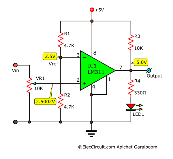
This circuit receives a fixed 5V regulated voltage supply. It is also used to determine the reference voltage (Vref) at pin 3 after adding R1 and R2 with the same values in the form of a voltage divider. Doing this sets the Vref—or voltage at pin 3—at half that of the supply voltage, that is, 2.5V.
Suppose that we want LED1 to light up when Vin exceeds 6V, like 6.002V, for example. We will apply 6V to Vin and then use VR1—which also functions as a voltage divider—to adjust the voltage to pin 2 to be 2.5V. The moment that Vin exceeds 6V, the voltage at pin 2 would also exceed 2.5V, even by just 0.0002V, and the LED1 would immediately light up because the state of the output switches from “low” to “high” of about 5V. Lastly, R3 increases the stability of the circuit.
Basic Inverting Comparator Circuit
Another usage of the LM311 is to use it as an inverting comparator. In the circuit below, we want the output to have a negative pulse when the input is higher than Vref.
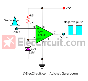
Basic inverting comparator circuit using LM311
Compared to the previous circuit, the reference voltage pin is now pin 2 instead of pin 3. When Vin goes higher than Vref, the output will be “low,” whereas when Vin goes below Vref, the output switches to “high.” If you want to read more about the actual usage of this circuit, click here: [link]
Square Wave Oscillator Circuit
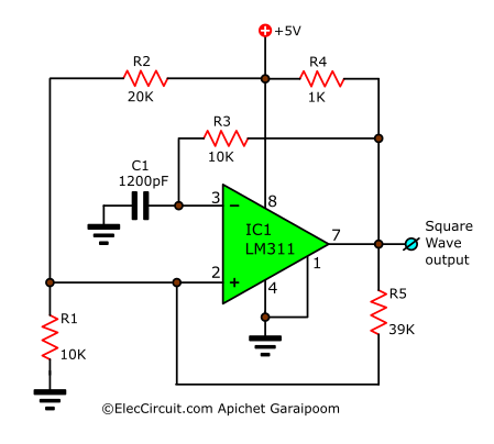
Apart from using it as a comparator, the LM311 could also function as an oscillator. This square wave generator circuit generates a square wave signal at a frequency of 100kHz; the frequency can be changed with the capacitance of C1.
Conclusion
In our experience, we found ourselves mostly using the LM311 in a compact comparator circuit since that is what this chip was originally intended for. It is also small, having the same package as the 555 timer. Further, it works with a wide range of voltages, from single to dual supply and from 2.5V to 30V. This chip could also work together with TTL and CMOS chips with ease. Plus, it is stable and straightforward to design a circuit with.

I love electronics. I have been learning about them through creating simple electronic circuits or small projects. And now I am also having my children do the same. Nevertheless, I hope you found the experiences we shared on this site useful and fulfilling.