LM8560 is digital clock circuit IC that electronic amateurs are most interested. And The clock ICs that most popular are LM8361, MM5387, Unfortunately, these ICs looking for will be difficult.
I highly recommend this clock circuits features to work for less than the original circuits. But there are advantages due to having output in Duplex LED display model, so reduce the number of wires between IC1 (LM8560) and LED display was 2 times more than the original.
Note: Also this projects we can use Jumbo digital clock using simple CMOS ICs
The clock working
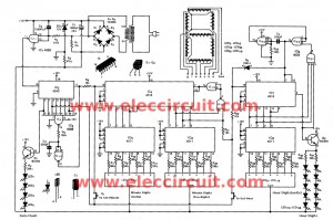
In this circuit, the heart of the circuits are IC1 (LM8560), Which has output the 3 way are:
1. The output for drive display Duplex Model numbers (pin 1-14)
2. The output provides alarm signal at pin 16.
3. The output to control electrical appliances with automatic timer.
Two R1, C1 together with was integrating circuit to Provide input to the clock signal 50 Hz input lock pin (pin 25) of IC1.

Two diode D1, D2 are the switch signal generators to the cathode of display number for working alternately and relation with the input of IC1. The alarm signal from pin 16 of IC1, will be entered to the potentiometer P1(Volume), to pin 3 of IC2 (LM386), that is alarm signal amplifiers to drive the loudspeaker.
The P1 so is fine an alarm sound pressure as you want. And the sleep out signal from pin 17 that you can continue to use, to control another circuit.
how to set the time
1. Press the switch S6 to set hours.
2. Press the switch S4 to set minutes.
To set the alarm time
1. Press the switch S3 to hold down.
2. Press the switch S5 to set hours.
3. Press the switch S4 to set minutes.
When the time limit, the alarm signal will ring. Press switch S2 or other switches to stop the alarm sound.
– Cancel the alarm system, press S2 to hold down.
To set the time turn on- off the Electric appliance.
1. Press switch S6
2. Press switch S4 to set minutes, Time to show the remaining time.
3. Press switch S5 to set hours.
Time dilation alarm to repeat alarm.
In the case of alarm circuit operation and we want to Repeat alarm. To extended for another nine minutes, with the press of a switch S7. The output signal for control turn on-off electric appliance circuit, get from pin 17 of IC1.
Detail of parts
IC1: LM8560B DIGITAL ALARM CLOCK
IC2: LM386 audio amplifier chip
D1, D2, D3_1N4001 50V 1A Diodes
0.25W 5% Resistors
R1: 100K 1/4w resistor
R2, R3: 120Ω
R4: 91K
R5: 10Ω
Volume P1: 10K Potentiometer
C1, C5: 0.01uF 50V Polyester Capacitor
C2: 470uF 16V Electrolytic Capacitors
C3, C4: 0.1uF 50V Polyester Capacitor
C6: 10uF 16V Electrolytic Capacitors
C7: 100uF 16V Electrolytic Capacitors
DIP LED DISPLAY_6052X-S
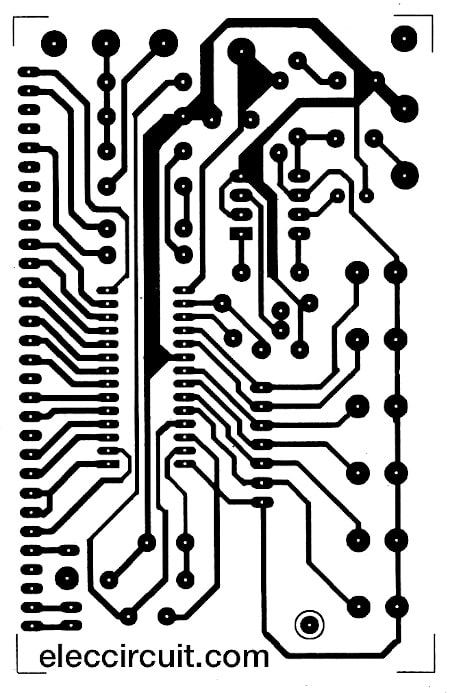
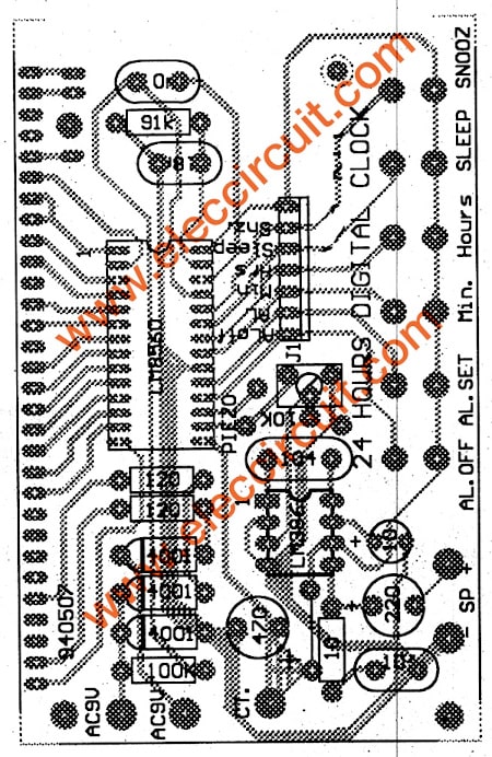
Builds LM8560 clock circuit
-You place the electronic components on the PCB board correctly completed, as shown in the picture, The display numbers can use bent wire to perpendicular. Then soldered directly to the PCB and LED display.
Note: PCB layout print in 300 dot per inch
-These switches you are able to put directly on PCB.
-You can choose display is 12 hours with open pin 28.
– If you want to connect a battery backup to the circuits continues to operate, even when the power goes out. You just connect the 9-volt battery, by the negative terminal join to diode 1N4001 into pin 20 of IC1 and the positive terminal at pin 28.
-To work range power clock cycle will continue. But it will not display on the screen.
-If do not has the backup power supply when the power goes out then restart display circuit will blink.
We recommend these below
- LM8365 alarm digital clock for beginners
- Jumbo digital clock using simple CMOS ICs
- MM5369 60Hz calibration frequency
I love electronic circuit. I will collect a lot circuit electronic for teach my son and are useful for everyone.

this digital clock uses 50 Hz house supply line as time but in case of power supply failure it will not work.if a CRYSTAL oscillator is used with circuit it will be most usefull.
Cheap Digital time clock with alarm circuit
Hey please send me the original pcb layout file i want to build the clock like yours.I shall be thankful to you.Have a great day…!
hi! can i have a copy of the program? please. thank you in advance
Hi,
This looks really interesting. Can you send me a copy of the PCB layout?
Thanks,
Hello,
I am a 14 year old boy and i am making this project for a school assignment as well as a birthday/Christmas present.
In the 1st picture i want to know, what S1 is? and where it is placed in the PCB?
Jared
how can it works with out ac 220
how can it works with outac220
hi, where can i get the duplex display? looking for one right one.. please let me know asap.. anybody?
Hi, John
You can find at amazon.com : https://t.co/5L8XIcQAC6
OR
This project is easier than one :https://www.eleccircuit.com/jumbo-digital-clock-using-simple-cmos-ics/
Dude..!! What is the purpose of LM386 in this circuit. Is it capable of driving speaker for speaking clock….!???
How can we place am/pm indicator in this circuit
How can we use this circuit to display seconds in numbers instead of two dots.
Can we use TDA7052 as IC2
the above digital clock circuit easy to understand at the samme time the parts are available in the market i need this clck please sent its price thanking you
hi..
what is the power rating of transformer t1. is it 9-0-9
. The switch s1 is missing. Is it power on/off switch
in description u said that “If you want to connect a battery backup to the
circuits continues to operate, even when the
power goes out. You just connect the 9 volt
battery, by the negative terminal join to diode
1N4001 into pin 20 of IC1 and the positive
terminal at pin 28”
I think +ve terminal join to diode and -ve to 28.
isn’t it..?
please give me a replay.. i wanna do this thing..
please send me the pcb diagram
Hi Selva,
Thanks for you feedback, please look in PCB layout and component layout.
Please give the pcb layout size for printout on glossy paper.
please i need the pin confirguration of the duplex display 🙂
hi please send me the the pcb layout please
can you send me please
Hi lewis,
Here is PCB layout: https://www.eleccircuit.com/wp-content/uploads/2012/09/PCB-of-Cheap-Digital-time-clock-with-alarm-circuit-by-LM8560.jpg
Oops! That page can’t be found.
Please check
No40,Jalan5,Taman Sungai Mas,34000 Taiping,Perak
Can i know where to buy duplex display in malaysia
can you tell me where to get the duplex display please? my search didnt come up any information about this part.
Hi,
would this circuit work on 5v and how much power
it consumes.
Hi
duplex display is not needed, if you have interface. I built this : https://www.hobbielektronika.hu/forum/topic_634.html
with name: (#)morfi007
I used 4 standard common anode displays: LD-S100UB-C
sorry
https://www.hobbielektronika.hu/forum/topic_634.html?pg=1424
i found duplex display but it 20 leg???
how about the pcb size generally . pls tell me.
Whear can I perches ful kit?
what other displays could be used with this?
I have prepared one for me … I just want to add 20 LEDs/segment of the display. I have seen if I put 5 LEDs/segment, then I get desired luminosity /brightness from the LEDs, But if I increase the number of LEDs/segment, then it wont glow . Might be due to voltage drop. Please suggest what can be done in this scenario.
Hi.i,d like to add a regulator ic to the clock diagram because when ac220 v of the city is weak,the clock doesn,t work correct
Hi Askar Alibolandi,
Thanks for your question.
I am sorry, this circuit needs AC line to generate a DC pulse 50HZ.