Designing a 3 Transistors Amplifier Circuit in a Simple Way
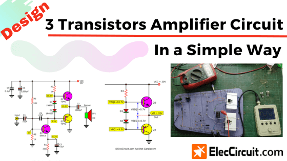
Learn electronics by designing 3 transistor amplifier circuit in simple way. With driving power of 1W – 7W. Or higher amplifier convenience. Read more
Learn electronics by designing 3 transistor amplifier circuit in simple way. With driving power of 1W – 7W. Or higher amplifier convenience. Read more
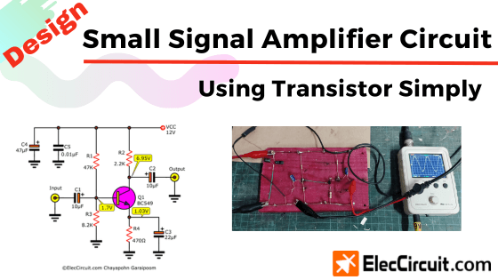
We are going to learn how to design a small signal amplifier circuit using transistors in a simple way, with class A amplifier form. Read more
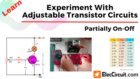
In the previous articles, we learned about using a transistor as a switch, that was, either completely on or off. But circuits such as the audio amplifiers will require the transistor to be partially on, which is very interesting. But it can be quite a difficult subject for beginners who just started learning electronics to … Read more
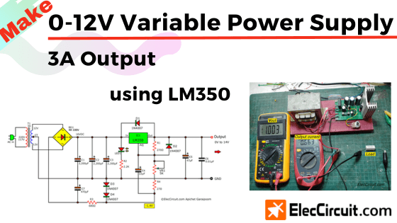
In a normal circuit, the general LM350 regulator has a start voltage of 1.25V. But this circuit is special that start of 0-volts. We use only one IC and a few other components. So cheap and easy for you. Read more
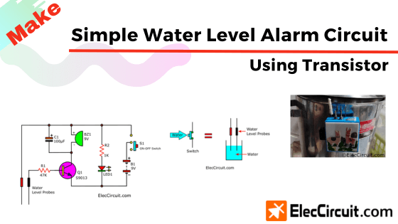
It worked by sounding an alarm when the water level rose to the set level. So we can close the water valve in time and prevent an overflow. Read more