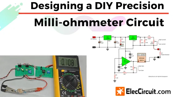
Today, we are going to build our own milliohmmeter circuit. The milliohmmeter is a very useful tool used to measure minuscule amounts of resistance in resistors or other electronic components.
We will, like many of our other circuits, focus on utilizing existing resources to make this milliohmmeter circuit. The main component of which is the regulator ICs; as for the voltmeter for displaying the resistance, we are using a common digital meter we have.
Aside from that, we will be learning electronics by designing circuits and determining basic electronic component values. The resulting circuit would be functional while being simple to make and understand.
Our Reason to use a Milli-ohmmeter
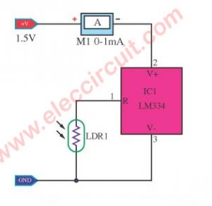
Not so long ago, we needed a 0.1Ω 5W resistor to use in a 2A ammeter circuit. However, we do not have a resistor of that value, and purchasing a new one takes time until it arrives. So we look for a way to adapt the resistors we already have, since it will be faster, and it is also a chance to clear out older components in our storage.
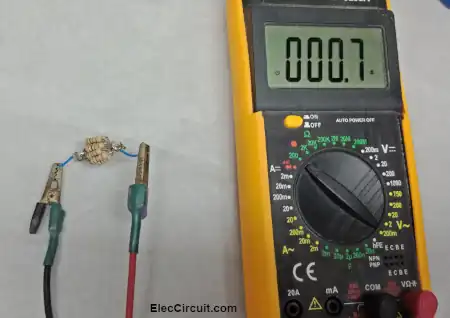
Coincidentally, we happen to have hundreds of 1Ω 0.5W resistors. According to the parallel circuit rule, connecting ten of them in parallel results in a total resistance of exactly 0.1Ω. Furthermore, the total wattage rating would also increase to 5W as needed.
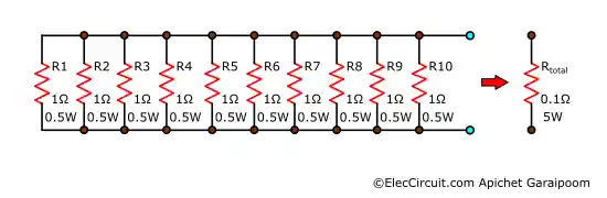
But after connecting the ten 1Ω 0.5W resistors, we want to make sure that the total resistance is exactly 0.1Ω as we calculated. Instead, measuring it with a conventional digital meter reads 0.7Ω.
We surmise this is because of the following two reasons: These old resistors in our storage have already deteriorated. Or our digital meter is broken (again). We like this digital meter because it is cheap, costing around $3. However, after using it for a while, some functions begin to fail; currently, only the DC measuring function still reads correctly.
Nevertheless, even if the tools are not ready, we will find another way. Every problem is a learning opportunity. Having fun with fixing the problem. A problem is not a failure but a part of the learning experience.
Ideal of Creating a Circuit to Measure Low Resistance
I once had a conversation with my friend who owns a cement factory. He told me about a type of ohmmeter that measures a very low resistance, around 0.000001Ω, called a microohmmeter. He used it to check for irregularity in the transformer or motor coils, as well as junctions, wires, and fuses. It gets used often when diagnosing electrical faults in the factory. Of course, this type of meter is essential, and it must be precise. He told me how he would use this meter as such:
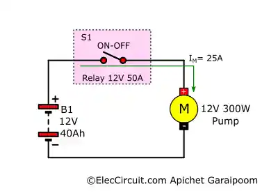
The contacts of a relay withstand up to 50A of current at 12V; thus, its internal resistance is about R = V/I = 12V/50A = 0.24 ohms. But after a long time, there is a deterioration in the contact faces, causing its resistance to drop to about 0.7 ohms. Subsequently, the current that flows over the relay decreases to I = 12V/0.7 = 17A, meaning that the current for the water pump also decreases.
Using a normal ohmmeter, it is almost impossible to measure resistance that low, which is why we need to use the microohmmeter or milliohmmeter.
Especially nowadays, when wire quality has gotten worse, the insulator is larger, but the actual conductor has gotten smaller. As a result, the wire’s internal resistance increases, causing it to conduct less current.
He also emphasized the one important point: safety. When using this meter to measure some components, there has to be absolutely no electricity within the circuit. If there is some electricity left, it can cause us harm or damage to the meter.
Below is an example of an aftermarket milliohmmeter. It has 4 wires set up, allowing for the separation of current-supply and voltage-measuring wires, which improves accuracy.

6‑Gear Digital Milliohmmeter, 4‑Wire Measurement DC Low Tester
On Amazon.com (Affiliated link)
Anyway, this one is a little bit overkill for us; we just need a milliohmmeter to demonstrate basic electronic principles. Plus, as you will see later, putting together a milliohmmeter from scratch is not too difficult.
The Basics of How a Milliohmmeter Works
The basics of how a microohmmeter or milliohmmeter works are that it will apply a constant current to the measuring subject, then read the voltage across it before using both values to calculate the resistance.
The constant current ranges from 1A, 10A, 0.1A, etc. And the voltage the meter reads is in the µV or mV range. Therefore, the resulting resistance will be in the range of only µΩ to mΩ.
Relationship Between Resistance, Current, and Voltage
Before getting started with the milliohmmeter, let’s review the basics of the relationship between current, voltage, and resistance. It stated that when current flows through a resistor, there will always be a voltage across said resistor.
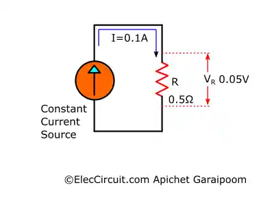
Suppose that a simple circuit consists of a constant 0.1A current source and a 1Ω or 0.5Ω resistor. If we measure the voltage across the resistor, it will read 0.1V and 0.05V, respectively. Which is in accordance with Ohm’s law:

Turning Ideas into a Circuit
The idea for measuring the resistance is to use a constant current source and apply this constant current to the component we are testing. Then, use a voltmeter to measure the voltage across the component; the resulting voltage will reflect the resistance in a DC voltage. It may sound complicated now, but you will understand better by the end of this.
Current Source Circuit
First and foremost, we need a constant current source that can supply a stable 0.1A current. We have many choices here, including using transistors and ICs. At the moment, we have many 7805s and LM317s in stock, so we are going to use these two.
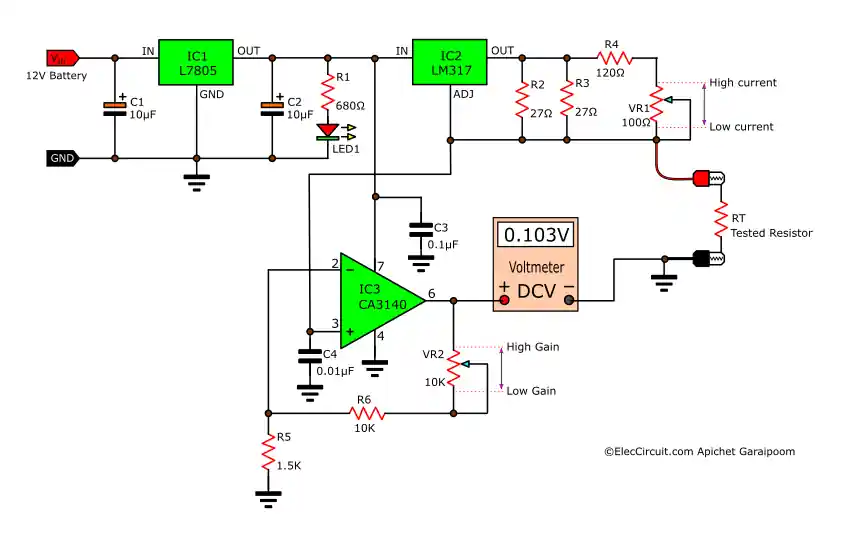
We are arranging them into a circuit in the same way as shown in the block diagram below.
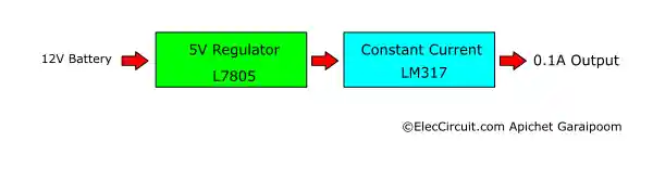
We decided that the original power source is a 12V battery because it produces less signal noise. In addition, we could replace it with an equivalent linear power supply capable of supplying 1A or more current.
The next step is the 5V regulator circuit. We are using the L7805 for this job. And since the L7805 is a one-chip 5V regulator solution, we only need to add C1 and C2 filter capacitors to increase the efficiency and decrease noise.
The next part is quite interesting: the constant current source. For today, we are using the LM317. We have used this chip before to build an Ni-HM battery charger in the past. If you are interested, you can read more about that here.
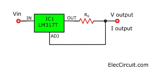
The important point is the value of RS, which is calculated by:

Whereby Vref = 1.25V and Iout = 0.1A.

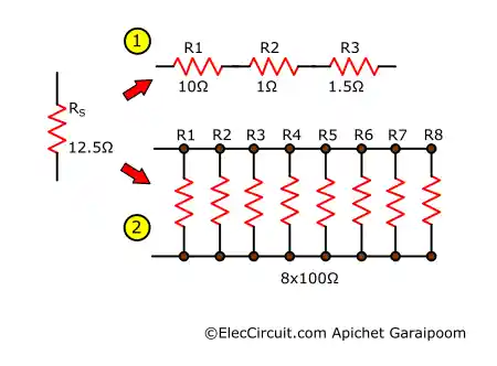
Since 12.5Ω is not a standard resistor value, we would need to make one. There are two ways to do this. The first way (1) involves connecting 10Ω, 1Ω, and 1.5Ω resistors in series to form a single 12.5Ω resistor.
The second way (2) is to connect eight 100Ω 0.5W resistors in parallel. This results in a 4W resistor (0.5Wx8), increasing circuit stability and durability.
However, neither of these methods is an ideal option. In reality, even if we make sure that RS has the exact resistance that we need, the output current will still deviate from the calculation. This may be because of other factors that we cannot keep track of. Therefore, it is a better practice to make RS adjustable so that we can easily tweak the output current.
Potentiometer for Current Adjustment
At first, we thought that we could just use a single trimpot (potentiometer), but the smallest one we have at the moment is 100Ω, which is going to make adjusting very tedious. Plus, a potentiometer can only withstand so much current.
So, the solution is to parallel it with other resistors. Let’s see how it’s going to work.
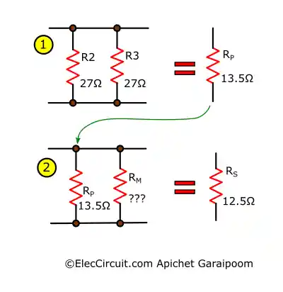
First (1), we have to find the two resistors (R2 and R3) that, when in parallel, will have the closest resistance to 12.5Ω (RS). We end up with two 27Ω resistors that, when parallel, have 13.5Ω resistance (RP).
Second (2), we have to find the resistance of RM in parallel with RP so that we can get the 12.5Ω we need.
We are using the following parallel resistance formula:
RS = (RP*RM)/(RP+RM)

But when finding RM, we have to rearrange the formula to:

After a bit of rounding up, RM = 170Ω. For us to be able to adjust the output current, the RM has to be a resistor (R4) in series with VR1. But how are we going to determine the resistance of R4?
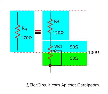
We use a simple concept whereby we set the 100Ω VR1 to its middle value (50Ω), then find the difference to the RM (170Ω):

We will use these resulting values to build a constant current circuit.
But lastly, let’s attempt to find the maximum output current (Imax). We adjust the VR1 to its lowest value of 0Ω; as a result, RM is now equal to 120Ω (the resistance of R4).

Conversely, to find the minimum output current (Imin), we will have to adjust VR1 to the max of 100Ω. Therefore, RM is equal to 220Ω (R4+VR1).

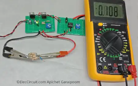
Testing the Circuit
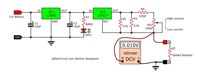
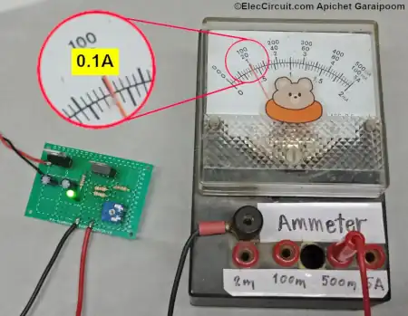
After assembling the circuit on a perforated board according to the schematic above, we will use an ammeter to measure the output current. The result from the reading should be a constant 0.1A. However, if this is not the case, we will need to adjust VR1 until the output current is exactly 0.1A.
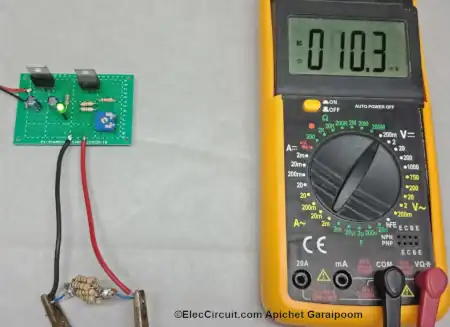
Next, add the test resistor to the output and measure the voltage across it using a voltmeter. The result we get for a 0.1Ω resistor is 10.3mV (0.01V), which is in accordance with the calculation we did at the start.
However, this may sound confusing, as we measure voltage in units of V but read it as resistance in units of Ω. For example, when measuring a 0.5Ω resistor, the voltmeter will display 0.05 instead of 0.5 for 0.5Ω.
There are two methods of solving this problem.
First, increase the constant current to 1A. This will cause the voltage across the resistor to be the same as its resistance; in this case, 0.5V. But this might not be appropriate, because a higher current will cause the ICs to heat up more, and more energy will be wasted.
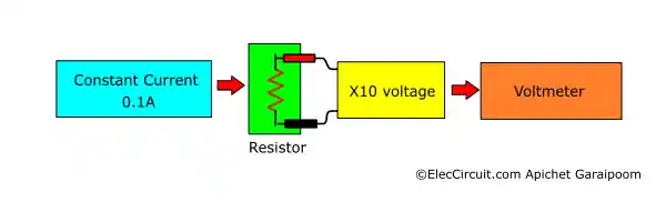
Second, we keep the constant current the same at 0.1A, but multiply the resulting voltage measurement by ten. With this method, we do not have to recalculate the resistance value for the circuit. It will make reading the value more convenient, as now 0.1 in the voltmeter is analogous to 0.1Ω resistance.
Amplify the Reading Voltage using CA3140 OP-AMP
The second method is better, so we are doing it that way using the CA3140 OP-AMP. This chip will increase the voltage by ten times. Our reason for using this IC is that it has a very high input impedance, resulting in less distortion.
Furthermore, the CA3140 requires a minimum of 4V to operate, so powering it with the 5V regulator already in the circuit is okay.
We adjust VR2 until the reading on the voltmeter is 0.1V when measuring a 0.1Ω resistor. Then, try to measure other low-resistance resistors. We tried a 0.5Ω one, and the reading showed correctly at 0.5V.
Nevertheless, we are not going to use this circuit that frequently; it is more akin to an experimental circuit. Also, it is only suitable for measuring resistance less than 3Ω because the output voltage of CA3140 is capped at 3V.
Conclusion
We hope that you had fun with this simple electronics experiment. With that said, this circuit could also be useful, such as for testing switch contacts or wires that carry large amounts of current.
For example, if you happen to have a 12V 10A DC motor and use a relay to control it, and you notice that the motor is not working at its full potential. This may be because of erosion at relay contacts, wires, or wiring junctures. At these potential failure points, the resistance would normally have been as low as 0.1Ω or less. However, erosion or loose joints can increase resistance to up to 0.5Ω. If this is the case, the current may be reduced to 24A rather than the usual 120A.
This circuit is not meant to be an alternative to an expensive, professional-grade microohmmeter. This circuit is but a way to learn about measuring low resistance values and basic electronics in general by way of solving simple electrical problems. We hope that this article is useful to you.
GET UPDATE VIA EMAIL
I always try to make Electronics Learning Easy.

I love electronics. I have been learning about them through creating simple electronic circuits or small projects. And now I am also having my children do the same. Nevertheless, I hope you found the experiences we shared on this site useful and fulfilling.