The LM337 is an adjustable negative voltage regulator. As the name suggests, it can supply an adjustable negative voltage from -1.2V to -37V at a current of 1.5A or more. It also comes with many protection features, such as thermal and short-circuit protections.
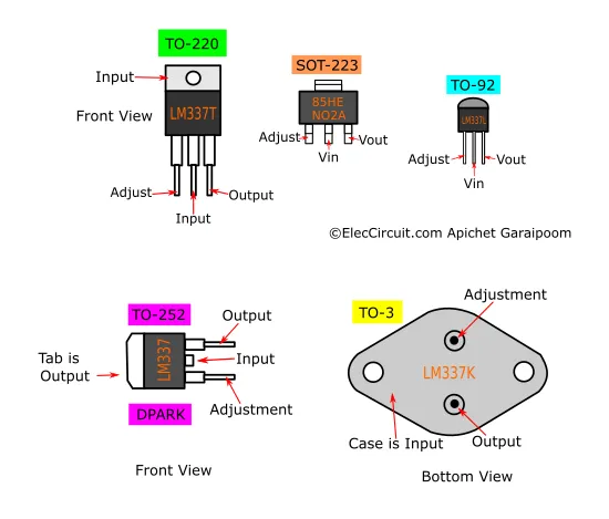
This chip can be used to build a fixed negative voltage regulator with the addition of a couple of components or an adjustable negative voltage regulator employing a potentiometer. The LM337 regulator is available in a TO-220, TO-03 metal can, SOT-223 SMD package, and more.
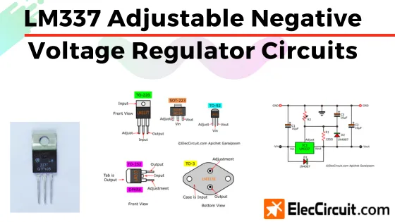
LM337 3-terminal Adjustable Negative Voltage Regulator
About 30 years ago, when I was first getting into electronics, I bought three pairs of LM337 and LM317, which back then were made by Motorola. I bought them in pairs because I thought that they were going to be used at the same rate. However, I rarely use the LM337, if at all; to this day, I still have two out of the original three in storage.
With that being said, not so long ago I built a cheap LM317 regulator circuit, expecting that it would deliver about 1.2A at a voltage of about 11.5V. However, in reality, it is only supplying about 0.8A at that voltage, meaning that the quality of this cheap LM317 may not be as good as I anticipated. So instead I switch the LM317 out for the LM337 I have, then reverse the voltage, and it delivers current exactly as I wanted.
This situation tells me that sometimes older, rarely used components may still be better than some newer, lower-quality ones. Therefore, maybe it’s time to check your cold storage looking for some of those components and find a use for them.
Features
- Adjustable output voltage range from -1.2V to -37V
- Typical output current of 1.5A
- Internal short-circuit and over-temperature protection
- Line regulation typically 0.01%/V
- Load regulation typically 0.3%
- Excellent thermal regulation, 0.002%/W
- 77 dB ripple rejection
- Excellent rejection of thermal transients
- 50 ppm/˚C temperature coefficient
- P + Product Enhancement tested
- Standard 3-lead transistor package
Pinouts
Learn more Datasheet
Example LM337 Circuits
Using the LM337 is quite simple, but how can we design a circuit that fully utilizes its capabilities? Let’s look at some example circuits below.
Basic LM337 Adjustable Negative Voltage Regulator Circuit
Let’s first look at the basic adjustable negative voltage regulator configuration for the LM337. We would also get to learn how to calculate the output voltage and the basic circuit structure.
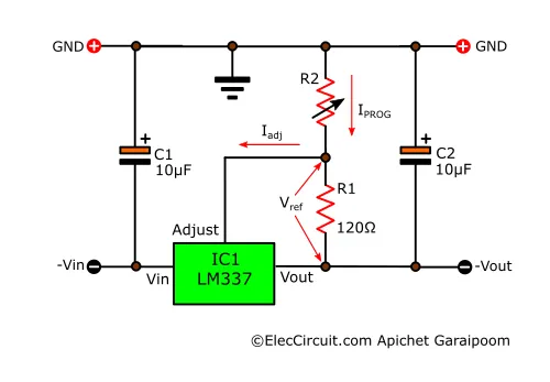
To find the Vout for this circuit, we need to use the following formula.
Vout = Vref (1+ R2/R1) + (IADJR2)
The LM337 keeps the reference voltage (Vref) between the Adjust and Vout pins at -1.25V and limits the IAdj to a constant 100μA. The main factors for the output voltage are R1 and R2. R1 is recommended to be 120Ω to maintain the aforementioned Vref. R2 may be a 5kΩ potentiometer so that we can adjust the output voltage.
Or if calculating is not what you fancy, you could also pick an R1 and R2 combination for each output voltage from the list below.
List of Output Voltages per R1 and R2
1.43V : R1 = 470Ω, R2 = 68Ω
1.47V : R1 = 470Ω, R2 = 82Ω
1.47V : R1 = 390Ω, R2 = 68Ω
1.51V : R1 = 330Ω, R2 = 68Ω
1.51V : R1 = 390Ω, R2 = 82Ω
1.52V : R1 = 470Ω, R2 = 100Ω
1.53V : R1 = 390Ω, R2 = 82Ω
1.56V : R1 = 330Ω, R2 = 82Ω
1.57V : R1 = 270Ω, R2 = 68Ω
1.57V : R1 = 470Ω, R2 = 120Ω
1.57V : R1 = 390Ω, R2 = 100Ω
1.59V : R1 = 390Ω, R2 = 100Ω
1.60V : R1 = 240Ω, R2 = 68Ω
1.63V : R1 = 330Ω, R2 = 100Ω
1.63V : R1 = 270Ω, R2 = 82Ω
1.64V : R1 = 390Ω, R2 = 120Ω
1.64V : R1 = 220Ω, R2 = 68Ω
1.65V : R1 = 470Ω, R2 = 150Ω
1.66V : R1 = 390Ω, R2 = 120Ω
1.68V : R1 = 240Ω, R2 = 82Ω
1.71V : R1 = 330Ω, R2 = 120Ω
1.71V : R1 = 270Ω, R2 = 100Ω
1.72V : R1 = 220Ω, R2 = 82Ω
1.72V : R1 = 180Ω, R2 = 68Ω
1.73V : R1 = 470Ω, R2 = 180Ω
1.73V : R1 = 390Ω, R2 = 150Ω
1.76V : R1 = 390Ω, R2 = 150Ω
1.77V : R1 = 240Ω, R2 = 100Ω
1.81V : R1 = 270Ω, R2 = 120Ω
1.82V : R1 = 150Ω, R2 = 68Ω
1.82V : R1 = 330Ω, R2 = 150Ω
1.82V : R1 = 180Ω, R2 = 82Ω
1.83V : R1 = 390Ω, R2 = 180Ω
1.84V : R1 = 470Ω, R2 = 220Ω
1.86V : R1 = 390Ω, R2 = 180Ω
1.88V : R1 = 240Ω, R2 = 120Ω
1.89V : R1 = 470Ω, R2 = 240Ω
1.93V : R1 = 330Ω, R2 = 180Ω
1.93V : R1 = 150Ω, R2 = 82Ω
1.94V : R1 = 270Ω, R2 = 150Ω
1.96V : R1 = 390Ω, R2 = 220Ω
1.97V : R1 = 470Ω, R2 = 270Ω
1.99V : R1 = 390Ω, R2 = 220Ω
2.02V : R1 = 390Ω, R2 = 240Ω
2.03V : R1 = 240Ω, R2 = 150Ω
2.06V : R1 = 390Ω, R2 = 240Ω
2.08V : R1 = 330Ω, R2 = 220Ω
2.10V : R1 = 220Ω, R2 = 150Ω
2.12V : R1 = 390Ω, R2 = 270Ω
2.13V : R1 = 470Ω, R2 = 330Ω
2.16V : R1 = 330Ω, R2 = 240Ω
2.16V : R1 = 390Ω, R2 = 270Ω
2.19V : R1 = 240Ω, R2 = 180Ω
2.23V : R1 = 470Ω, R2 = 390Ω
2.25V : R1 = 150Ω, R2 = 120Ω
2.27V : R1 = 270Ω, R2 = 220Ω
2.27V : R1 = 330Ω, R2 = 270Ω
2.29V : R1 = 470Ω, R2 = 390Ω
2.29V : R1 = 180Ω, R2 = 150Ω
2.31V : R1 = 390Ω, R2 = 330Ω
2.36V : R1 = 270Ω, R2 = 240Ω
2.37V : R1 = 390Ω, R2 = 330Ω
2.40V : R1 = 240Ω, R2 = 220Ω
2.44V : R1 = 390Ω, R2 = 390Ω
2.50V : R1 = 470Ω, R2 = 470Ω
2.57V : R1 = 390Ω, R2 = 390Ω
2.61V : R1 = 220Ω, R2 = 240Ω
2.65V : R1 = 330Ω, R2 = 390Ω
2.66V : R1 = 240Ω, R2 = 270Ω
2.73V : R1 = 330Ω, R2 = 390Ω
2.74V : R1 = 470Ω, R2 = 560Ω
2.75V : R1 = 150Ω, R2 = 180Ω
2.76V : R1 = 390Ω, R2 = 470Ω
2.78V : R1 = 270Ω, R2 = 330Ω
2.78V : R1 = 220Ω, R2 = 270Ω
2.84V : R1 = 390Ω, R2 = 470Ω
2.92V : R1 = 180Ω, R2 = 240Ω
2.96V : R1 = 270Ω, R2 = 390Ω
2.97V : R1 = 240Ω, R2 = 330Ω
3.03V : R1 = 330Ω, R2 = 470Ω
3.05V : R1 = 390Ω, R2 = 560Ω
3.06V : R1 = 270Ω, R2 = 390Ω
3.06V : R1 = 470Ω, R2 = 680Ω
3.08V : R1 = 150Ω, R2 = 220Ω
3.13V : R1 = 220Ω, R2 = 330Ω
3.14V : R1 = 390Ω, R2 = 560Ω
3.18V : R1 = 240Ω, R2 = 390Ω
3.25V : R1 = 150Ω, R2 = 240Ω
3.28V : R1 = 240Ω, R2 = 390Ω
3.37V : R1 = 330Ω, R2 = 560Ω
3.43V : R1 = 270Ω, R2 = 470Ω
3.43V : R1 = 390Ω, R2 = 680Ω
3.43V : R1 = 470Ω, R2 = 820Ω
3.47V : R1 = 220Ω, R2 = 390Ω
3.50V : R1 = 150Ω, R2 = 270Ω
3.54V : R1 = 180Ω, R2 = 330Ω
3.55V : R1 = 390Ω, R2 = 680Ω
3.70V : R1 = 240Ω, R2 = 470Ω
3.82V : R1 = 180Ω, R2 = 390Ω
3.83V : R1 = 330Ω, R2 = 680Ω
3.84V : R1 = 270Ω, R2 = 560Ω
3.88V : R1 = 390Ω, R2 = 820Ω
3.91V : R1 = 470Ω, R2 = 1K
3.92V : R1 = 220Ω, R2 = 470Ω
3.96V : R1 = 180Ω, R2 = 390Ω
4.00V : R1 = 150Ω, R2 = 330Ω
4.02V : R1 = 390Ω, R2 = 820Ω
4.17V : R1 = 240Ω, R2 = 560Ω
4.33V : R1 = 150Ω, R2 = 390Ω
4.36V : R1 = 330Ω, R2 = 820Ω
4.40V : R1 = 270Ω, R2 = 680Ω
4.43V : R1 = 220Ω, R2 = 560Ω
4.44V : R1 = 470Ω, R2 = 1.2K
4.46V : R1 = 390Ω, R2 = 1K
4.50V : R1 = 150Ω, R2 = 390Ω
4.51V : R1 = 180Ω, R2 = 470Ω
4.63V : R1 = 390Ω, R2 = 1K
4.79V : R1 = 240Ω, R2 = 680Ω
5.04V : R1 = 330Ω, R2 = 1K
5.05V : R1 = 270Ω, R2 = 820Ω
5.10V : R1 = 390Ω, R2 = 1.2K
5.11V : R1 = 220Ω, R2 = 680Ω
5.14V : R1 = 180Ω, R2 = 560Ω
5.17V : R1 = 150Ω, R2 = 470Ω
5.24V : R1 = 470Ω, R2 = 1.5K
5.30V : R1 = 390Ω, R2 = 1.2K
5.52V : R1 = 240Ω, R2 = 820Ω
5.80V : R1 = 330Ω, R2 = 1.2K
5.88V : R1 = 270Ω, R2 = 1K
5.91V : R1 = 220Ω, R2 = 820Ω
5.92V : R1 = 150Ω, R2 = 560Ω
5.97V : R1 = 180Ω, R2 = 680Ω
6.04V : R1 = 470Ω, R2 = 1.8K
6.06V : R1 = 390Ω, R2 = 1.5K
6.32V : R1 = 390Ω, R2 = 1.5K
6.46V : R1 = 240Ω, R2 = 1K
6.81V : R1 = 270Ω, R2 = 1.2K
6.92V : R1 = 150Ω, R2 = 680Ω
6.93V : R1 = 330Ω, R2 = 1.5K
6.94V : R1 = 180Ω, R2 = 820Ω
7.02V : R1 = 390Ω, R2 = 1.8K
7.10V : R1 = 470Ω, R2 = 2.2K
7.33V : R1 = 390Ω, R2 = 1.8K
7.50V : R1 = 240Ω, R2 = 1.2K
8.07V : R1 = 330Ω, R2 = 1.8K
8.08V : R1 = 150Ω, R2 = 820Ω
8.19V : R1 = 270Ω, R2 = 1.5K
8.30V : R1 = 390Ω, R2 = 2.2K
8.43V : R1 = 470Ω, R2 = 2.7K
8.68V : R1 = 390Ω, R2 = 2.2K
9.06V : R1 = 240Ω, R2 = 1.5K
9.58V : R1 = 330Ω, R2 = 2.2K
9.77V : R1 = 220Ω, R2 = 1.5K
9.90V : R1 = 390Ω, R2 = 2.7K
10.03V : R1 = 470Ω, R2 = 3.3K
10.37V : R1 = 390Ω, R2 = 2.7K
10.63V : R1 = 240Ω, R2 = 1.8K
11.25V : R1 = 150 Ω, R2 = 1.2K
11.44V : R1 = 270Ω, R2 = 2.2K
11.48V : R1 = 330Ω, R2 = 2.7K
11.67V : R1 = 180Ω, R2 = 1.5K
11.83V : R1 = 390Ω, R2 = 3.3K
12.40V : R1 = 390Ω, R2 = 3.3K
12.71V : R1 = 240Ω, R2 = 2.2K
13.75V : R1 = 330Ω, R2 = 3.3K
15.31V : R1 = 240Ω, R2 = 2.7K
16.25V : R1 = 150Ω, R2 = 1.8K
16.53V : R1 = 270Ω, R2 = 3.3K
16.59V : R1 = 220Ω, R2 = 2.7K
18.44V : R1 = 240Ω, R2 = 3.3K
19.58V : R1 = 150Ω, R2 = 2.2K
20.00V : R1 = 220Ω, R2 = 3.3K
23.75V : R1 = 150Ω, R2 = 2.7K
24.17V : R1 = 180Ω, R2 = 3.3K
28.75V : R1 = 150Ω, R2 = 3.3K
We should also add two capacitors to the circuit to improve the performance and stability. C1 is necessary if the LM337 is further than 4 inches away from the power supply’s filter, and C2 is for the load stability. Both capacitors are recommended to be either a 1μF solid tantalum or a 10μF aluminum electrolytic.
Additionally, if you want to pull more than 200mA of current from the IC, you may need a heatsink to help dissipate the heat. At higher voltage and current of more than 500mA, without proper cooling, the LM337 may not be able to deliver current according to its specification or damage itself.
Adjustable Lab Voltage Regulator
Usually, we deploy the LM337 together with the LM317 as a dual voltage regulator that can supply positive and negative voltage. We can use this type of circuit as an adjustable lab dual voltage regulator for testing and experimenting purposes.
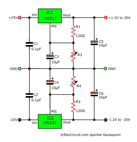
As shown in the circuit schematic above, Vin for both the negative and positive is 25V, and Vout ranges from +1.2V to +20V and -1.2V to -20V. R3 and R4 control the positive and negative output voltages, respectively. C3 and C4 prevent ripple voltage.
LM337 Negative Voltage Regulator with Protection Diodes
This circuit is quite similar to the previous circuit; the difference is the addition of two diodes and one capacitor, and they all have basic functions. C1 stops ripple voltage from passing through to the output. The two protection diodes prevent the capacitors from discharging into the LM337 during a short circuit. D1 blocks the discharge of C2, and D2 blocks that of C3.
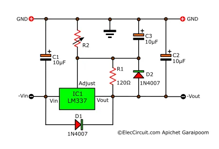
Some may have omitted the use of these protection components because without them the circuit would still function normally. However, it is better to be safe and add these components in, especially if the capacitors have high capacitance or the output voltage exceeds -25V.
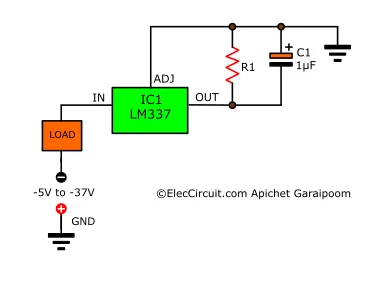
Adjustable Current Regulator
The LM337 has another interesting and useful function, which is the current regulator. It will keep the current constant even when the voltage increases or decreases. Current regulation or limiting is one of the main functions of a resistor. But whereas the current of a resistor increases as its voltage increases to the point of damaging the load, the LM337 does not have that issue.
The circuit below shows a basic implementation of the LM337 as a current regulator. The resistor R1 determines the output current (Ioutput), which we can calculate using the following formula:
Ioutput = 1.25V ÷ R1
However, it is advised that the resistance should be between 0.8Ω and 120Ω.
Precision LED Regulator Circuit
Now, let’s look at an LED circuit that uses the LM337 current regulator function. The LED in the circuit below is a 5mm green LED, and its current is I = 1.5V ÷ R1. So if we set R1 to be 100Ω, the LED’s current would be exactly 15mA. VR1 allows us to dial in the current; its adjustment range is about ±15%.
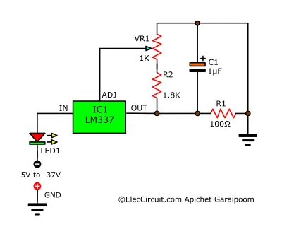
We could supply an input voltage within the range of -5V to -37V to this circuit, and the current that flows through LED1 would still be the same at 15mA. But if we only use a 100-ohm resistor, when the supplied voltage increases from 5V to 37V, the current over LED1 would be at an astronomical 300mA.
Buy LM337 at Amazon.com here (affiliated link)
Conclusion
The LM337 may often be a forgotten regulator IC because of its specific usage. But it was relatively good at its job as a negative voltage regulator. If you happen to have the LM337 in your storage, consider revisiting it. For instance, try increasing its output current by using an amplifier transistor or adapt it to other uses. In the future, we might explore more of this chip’s usages in greater detail.
GET UPDATE VIA EMAIL
I always try to make Electronics Learning Easy.

I love electronics. I have been learning about them through creating simple electronic circuits or small projects. And now I am also having my children do the same. Nevertheless, I hope you found the experiences we shared on this site useful and fulfilling.