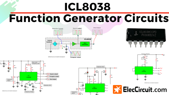
Today we will be using the ICL8038 voltage-controlled oscillator, or precision waveform generator, to create four function generator circuits. The ICL8038 can generate three output waveforms without many external components: a sine wave, a triangular wave, and a square wave.
Suppose you have just finished building a power amplifier. It sounds great during testing, though you notice some distortion. A good amplifier should only amplify the signal and not change its frequency or waveform.
So, you decide to measure its output signal with an oscilloscope to see its waveform. But first, you would need a known signal source before measuring the output, which a function generator can provide.
ICL8038 Waveform Generator
There are many ways to make a function generator. The ICL8038 waveform generator is another great option, as it has a wide frequency range from 0.001Hz up to 300kHz with some external components and a total of five waveform outputs.
It can simultaneously generate a square wave, a triangular wave, and a sine wave signal. However, adding an external timing resistor will allow for the output of two more asymmetrical waveforms: a sawtooth/ramp wave and a pulse wave signal.
General Features
- Frequency drift with temperature: 250ppm / °C
- Distortion (sine wave output): 1%
- Linearity (triangular wave output): 0.1%
- Output impedance: 200Ω @ 5mA
- Output frequency range: 0.001Hz to 300kHz
- Adjustable duty cycle: 2% to 98%
- Simultaneously output of a sine, a square, and a triangular wave
- Require a minimum number of external components
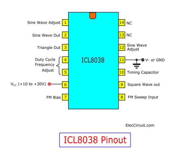
Pinouts
Frequency Generation
To massively simplify, inside the ICL8038, there are comparators and a flip-flop. Supposing a flip-flop is in an “off” state (low), an external capacitor gets charged. But when the capacitor voltage reaches ⅔ of the voltage supply, as compared by comparator 1, it will switch the flip-flop to an “on” state (high), which allows the capacitor to discharge and its voltage to decrease linearly.
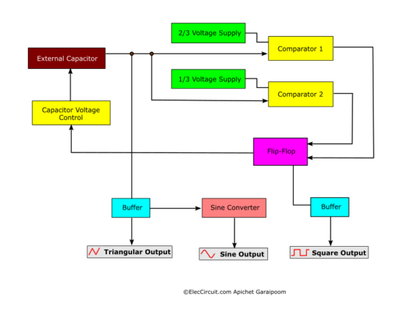
At this point, comparator 2 compares the capacitor voltage. When it reaches ⅓ of the supply voltage, the flip-flop is switched back to its previous off state, recharging the capacitor, and the cycle continues.
The capacitor’s linear charge and discharge cycle produce a triangular waveform, while the flip-flop’s switching between low and high produces a square waveform. Both waveforms are fed through a buffer before outputting to pins 3 and 9. A sine waveform is derived from the triangular wave using a non-linear network (sine converter) before being output to pin 2.
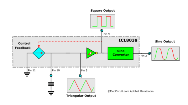
In conclusion, the ICL8038 can generate three waveforms, which can be summarized as follows:
- A triangular wave results from an external capacitor’s linear charge and discharge cycle.
- A square wave is generated by a flip-flop that acts according to the capacitor voltage.
- A sine wave is created by feeding a triangular wave through a sine converter.
Waveform Duty Cycle
The ICL8038 allows the installation of timing resistors—positioned at pins 4 and 5—to determine the waveforms’ duty cycle. These resistors are often adjustable potentiometers, so the timing can be adjusted on the fly.
Some circuits used two potentiometers as timing resistors, thus allowing for a finer timing adjustment. However, if the application only requires a 50% duty cycle, using one potentiometer for both pins is simpler.
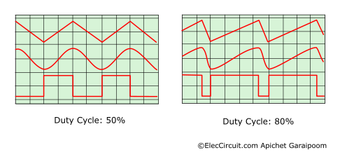
The resistor at pin 4 controls the raising of sine and triangular waves and the “high” of square waves, whereas pin 5 controls the falling and “low.” If both resistors have the same value, the duty cycle will be 50%. Below, we will discuss choosing the values of these components per individual circuit.
ICL8038 Circuits
There are four total circuits in this article, each with different upsides and downsides. You can choose which one fits your application best. Here is a summary of each circuit:
- The first circuit is the simplest of the bunch; it is the basic circuit.
- The second circuit is an improvement from the first, allowing for more customization.
- The third circuit is practical and has a great price-to-performance ratio.
- The fourth circuit is the most complex and flexible, with a greater adjustable frequency range and amplitude.
Basic ICL8038 Function Generator Circuit
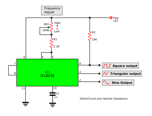
The main characteristic of this circuit is that it is straightforward and uses only three components: a potentiometer (VR1), two resistors (R1&R2), and a capacitor (C1) to determine the output frequency. The formula to calculate the output frequency is as follows:
The Components List
Resistors 0.25W 5%
R1: 2.2K
R2: 10K
VR1: 10K potentiometer
Capacitors
C1: See formula above
Semiconductor
IC1: ICL8038 precision waveform generator/voltage-controlled oscillator
Others
Universal PCB board
IC socket
Miscellaneous items used in assembly
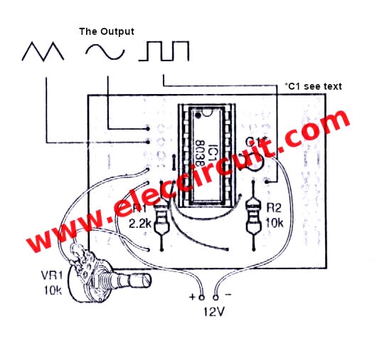
How to Builds
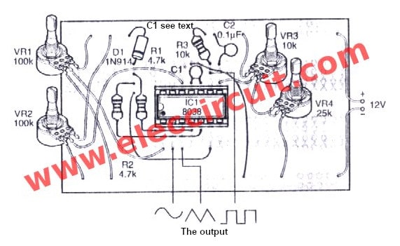
You can assemble the circuit on a universal PCB board using the layout shown below.
This first circuit was cheap but also had low performance. The next circuit is more suitable for real use and only uses a few more components.
Improved ICL8038 Function Generator Circuit
In this circuit, we can use a potentiometer to lower the sine wave distortion, thus improving its performance.
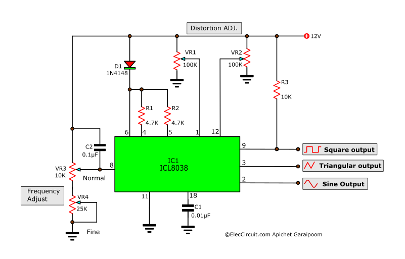
Now, let’s understand what each component does, starting with D1, R1, and R2. They determine the output signal symmetry, keeping it at a 50% duty cycle. VR1 and VR2 adjust the output’s sine waveform distortion. VR3 selects the desired frequency at the output, and VR4 further adjusts the frequency.
As for C1, it is used to determine the frequency range of the circuit, as shown in the table below.
| Frequency Range | C1 Value |
| 1Hz – 100Hz | 1uF |
| 100Hz-1KHz | 0.1uF |
| 1KHz-10KHz | 0.01uF |
| 10KHz-100KHz | 0.001uF |
The Components List
Resistors 1/4W 5%
R1, R2: 4.7K
R3: 10K
VR1, VR2: 100K(B) potentiometers
VR3: 10K(B) potentiometer
Capacitors
C1: See text
C2: 0.1uF(104) 50V Ceramic
Semiconductors
D1: 1N914 or 1N4148 75V 150mA diodes
IC1: ICL8038 precision waveform generator/voltage-controlled oscillator
Note: There are affiliate links on this post. This does not change the cost of the item for you. Thanks for your support.
How to Build
We can build this circuit using the component layout on the universal PCB board below.
Although this circuit improves on the first one, it still lacks some features. For instance, the adjustable output frequency range is limited even with VR1 and VR2. The circuit below offers a solution for this and other features.
ICL8038 Function Generator Circuit
This circuit offers a lot more practicality compared to the previous two circuits. Its general features are as follows:
- It has a single VR1 as a frequency adjust potentiometer and an S1 range selector, further increasing the frequency range and adjustability.
- It has an adjustable duty cycle using VR2.
- Its sine wave distortion can be adjusted through VR3.
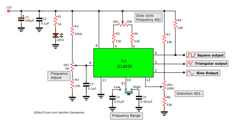
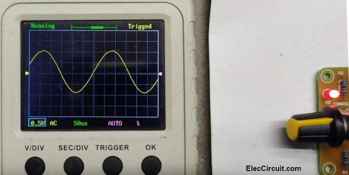
We actually built this ICL8038 function generator circuit—as shown below—using a circuit kit and have been using it since.
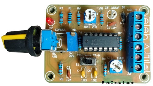
We mainly focused on the sine wave because we frequently used it to test audio amplifiers. This circuit delivers the sine wave signal quite well. However, we might need to adjust the distortion (VR3) and duty cycle (VR2) to achieve a better waveform.
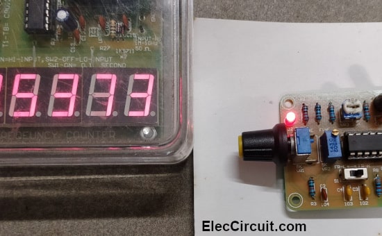
As for the output frequency, using S1 to select the range and VR1 to adjust within the range yields 53Hz to 538Hz in the low range and 539Hz to 5,373Hz in the high range, about a 5kHz max frequency.
ICL8038 Function Generator Circuit With Amplitude Adjustment
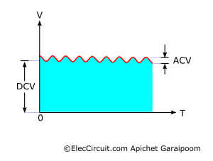
The circuit above works quite well; however, we notice that its sine wave always has an amplitude of 2Vp-p regardless of the frequency ranges. And we have no way of changing its amplitude. In addition, the output signal will be in the form of a DC signal that has a high-frequency AC signal on top.
In other words, if we want a function generator circuit with adjustable amplitude and an output buffer, we need to make a few changes to the previous circuit, which yields the circuit shown below.
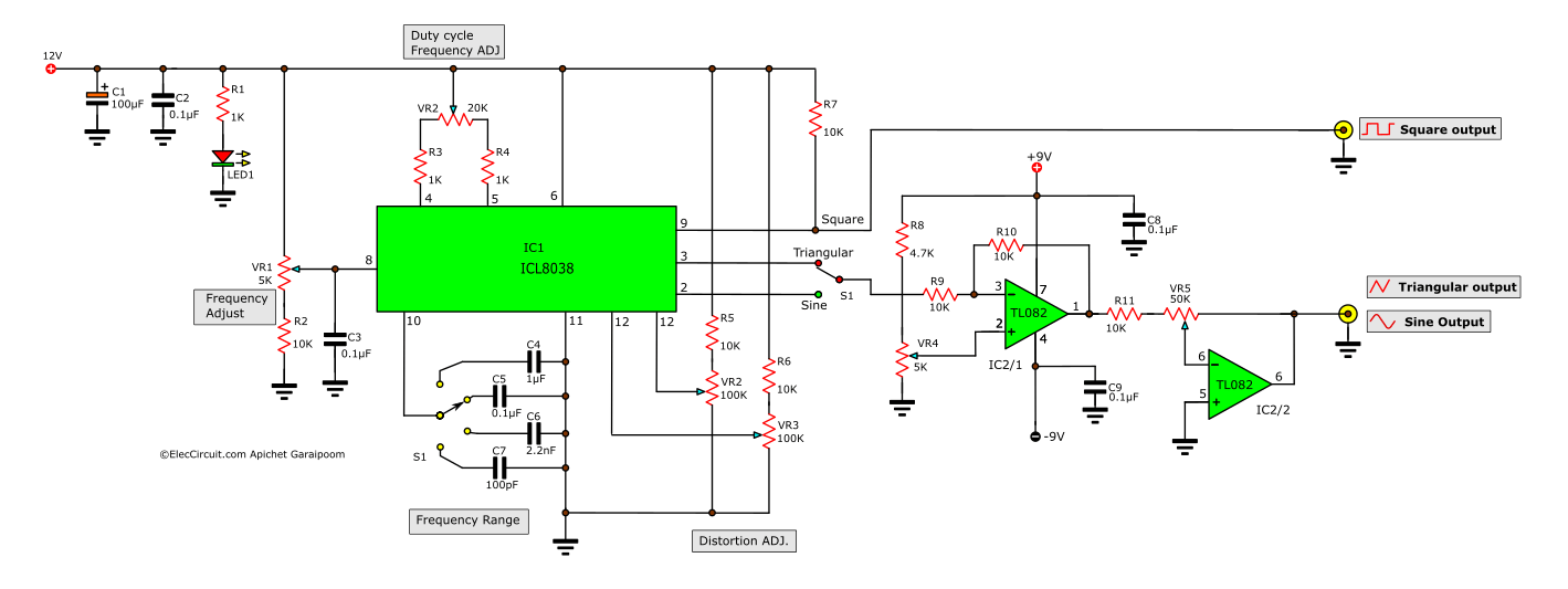
This circuit incorporates an amplifier circuit, IC2 TL082. The TL082 is an OP-AMP that can amplify signals over a wide frequency range, the highest of which is 4MHz. This makes it compatible with the ICL8038, and the TL082 is highly efficient due to the JFET input. It contains two individual OP-AMPs, allowing us to use it instead of two LM741s.
VR5 adjusts the amplifier’s amplitude or gain, whereas VR4 adjusts the offset value to obtain a full signal. The output will be approximately 9Vp-p. Furthermore, C4 to C7 broadens the frequency ranges, allowing for a total range of approximately 30Hz to 300KHz.
Note: This circuit has not been tested in practice, so we cannot confirm that it will work 100%. However, in principle, it should work. If you are interested in building it, please consider this risk.
Conclusion
The ICL8038 is a special-purpose IC that can be used to build a basic function generator circuit. It also has many features and is inexpensive. In our experience, it should be used based on the usage requirements. In the future, we may use it in other ways as well. Please stay tuned.
This circuit requires enough power supply. Do you have this one? If you do not have it. Look:Learn Many Power supply circuits

Written by: Apichet Garaipoom
Like many others, I started electronics with curiosity and simple circuits. Over time, I’ve found joy in sharing what I’ve learned—and now, I get to build with my kids. It’s a journey, and I hope this site helps you enjoy yours.
Read more about me
what is the amplification level generated by this circuit?? how to vary the amplitude levels?
Regarding Figure 1 schematic: There is an error in the wiring of the schematic: Wired as shown will burn the ICL8038:
Pin 6 needs +V and NOT pin 5. Pins 4 and 5 should be bridged.
Hi Peter Well spoted
I noticed this problem this moring after blowing one chip up
I have yet to test the circuit with the right connections in place
Thanks
Hello!
If you want to make the best Schumann generator, what is for you the best chip? ICL8038? XR2206? Can you please hep me? Thank you.
Francisco
Hello,
Would you provide boards for the ICL8035 generator?
Thank you!
Francisco
Helo,
Can you please supply the gerber files?
Thank you.
Francisco
Thank you… Thank you… Thank you,
your circuit will help me too much, because I am creating a free energy generator, & for that I am creating the mechanic part, & as I know, absolutely nothing at the electric part, your help is welcome.
Thank you again, best regards,
Paul Baroud
Hello
could you help me? I would like to drive a LED with a 8038 choosing from the 3 different wave forms and with a frequency range from 0.3 to 20 Hz
could it be done?
Hello,
Yes, You can use ICL8038 for this. It is quite easy.