Party is a lot of fun. Alcohol makes us happy. And. we should make an alcohol tester. Why? We do not need sad about it, right?
Imagine your friends who live in California, USA. He said that he likes to party with friends. With alcoholic beverages and the need to drive a car. He does not want illegal traffic and safety for everyone.
So, he needs to have the alcohol tester in a car. We agree. But… we are an electronic inventor. Can we build it? I highly suggested this circuit.
Advantage of it is easy to use. Show the alcohol level with the 10 LEDs. Use a few parts. So is not difficult to build and cheaper.
The working of the alcohol tester circuit
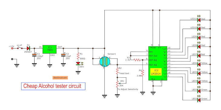
The heart of the circuit in Figure 1 is an alcohol sensor(sensor1), which features sensitive to the substances of alcohol.
When we apply the power supply of 12 volts into point J1 then turn ON switch S1 to provide the voltage supply to this circuit.
Figure 1 Cheap alcohol tester circuit
The voltage is maintained a level of voltage constant of 5 volts by IC1-LM7805. This voltage will be feed into all power of the circuit.
When considering that sensor1 pin 2 and pin 5 will be parts of heating coils inside the sensor body. It will be connected with the positive voltage to the ground makes generate heat up.
The input of the sensor is pin 1 and pin 3 is connected to voltage as well. The output of the sensor is the input pin 4 and pin 6 is connected to pin 5 of IC2-LM3914.
To apply the changes. From the sensors to manage with the LED2-LED11. To measure the alcohol content From the breath the test on the sensor.
The resistors R2 and VR1 serve to calibrate the voltage output from the sensor. More details, see the customization and the test projects.
When who tester blowing Breathing that within the alcohol onto the sensor unit. The vapors of Alcohol into contact with semiconductor components in the sensor, the Resistance to change within the sensors.
And have the output voltage to be applied to us. The heating coil will get rid of the alcohol vapor residues. Until the end From the first test. To ready for the next the test. For the first time after the calibration.
Testing alcohol tester circuit
First, need to understand the creation of this project. To is a personal alcohol tester only. Customization does not compare to the actual standard. But the volunteers really drink beer.
When Turn on will see the LED1 glow. Use hand covering the sensor, it will feel warm. Indicates that the machine is ready or waiting for 10-15 seconds. We measure the level of alcohol. Divided by the breath.
Here is video of it for Youtube channel by myvideoisonutube
Thanks a lot.
The normal level
The first is that we adjust VR1 until LED2, LED3 lights when the sensor is in its normal environment.
The middle level
In this test. Our Volunteers drank beer number two canned drinks on the wait 20 minutes before blowing. The test results can be seen LED4, LED5, LED6 bright yellow.
This means that Our body has alcohol in the blood. If necessary, drive the vehicle. Should stop drinking immediately. And the body stays about 20 minutes before driving on.
The high alcohol level.
If you continue to drink more. Blood alcohol level of the drink will be higher.
Test by the volunteers drank beer cans, three and four cans. When again try blowing found that the dismissal order LED7-LED11 will light up red. the test has shown that the level of alcohol too. Not suitable for driving any vehicle. Intoxication as a result of the slow and error. Should stop drinking and relaxing.

Written by: Apichet Garaipoom
Like many others, I started electronics with curiosity and simple circuits. Over time, I’ve found joy in sharing what I’ve learned—and now, I get to build with my kids. It’s a journey, and I hope this site helps you enjoy yours.
Read more about me
what sensor can i use on this detector?
Hi,magala felix
This is for example Analog Alcohol Sensor https://tinyurl.com/bf9y6c5
I hope it can help you.
How much does this testor cost
cd you inbox me your contacts
thank you
Hello. I am planning to build portable multi gas detector with LED display for my school project. I want to have 3 types of gas sensor which are,
1. harmful gas such as CO,
2. Oxygen content
3. Flammable gas such as propane and butane.
I have a problem to understand what I should do. Would you please recommend to me what should I do? What are the components should I prepare for the circuit. Can I have 3 types of sensor in one or I have to do it in separate part. For the power supply I am thinking to use 12 volt motorcycle battery. What are the costs for all the parts I need to buy? I am really appreciated if you can help me. Thank you very much.
hi. do you have the pcb layout for this? pls.. email me. thank you!
hi, do you have a layout of circuit for mq303a alcohol sensor
please have any one try to build this circuit and it learn well?
I need pcb layout for this
hi..i want to add a buzzer can you kindly show me the connection?thank you
what is cost for this cheap circuit???
Hi aniket,
Thanks for your feedback.
excellent project!what will i do if i add a buzzer.thank you..
Hi justice.
Thanks for your feedback.
Yes you can add buzzer in circuit.
the alchol tester circuit is not detecting , will u help me ..?
sir is the circuit working and whats the cost of the sensor in Indian Rupee
hello sir ,
I bought all d components of the circuit with MQ-3 sensor rather than a MQ-2. Im trying to connect the circuit but getting blank on
how to connect MQ-3 in circuit. the pins are not fitting in the breadboard and im fearing that soldering the sensor might damage the heating coil of the sensor. how can I connect the sensor to the circuit?
Hlo sir
The humen is really drunked or not????
because I think 2nd and 3rd led clow when human is in normal breathing
hii sir, i want pcb layout for this circuit.
how mach amount in this project sir
Apichet. Could you please provide a part number and a source for the alcohol sensor for this circuit thank you bob U S A
Hi robert dalley,
I’m not sure the alcohol sensor on http://www.amazon.com can use with this project. We want analog output voltage from this to input of LM3914. Now we have a lot of choices. For example https://amzn.to/2X1N3w2