As we may already know, in a digital signal there are only two states of voltage, the first being “high” and the other “low.” Signals with more than two states constitute analog signals, like audio signals, sine waves, et cetera. Applying these analog signals to a digital circuit directly would cause catastrophic problems because analog signals have a slow and variable switching speed.
The Schmitt trigger circuit will convert these constantly changing analog signals into two states, “high” and “low” or “1” and “0” digital signals. Hence, we can use a digital circuit to interpret or measure analog signals such as voltage levels, currents, temperatures, brightnesses, pressures, weights, speeds, and many others.
What is Schmitt Trigger?
A Schmitt trigger is a form of comparator circuit that is used to convert an analog signal to a digital signal. The trigger part of the name comes from the fact that the input voltage needs to reach a certain threshold point for the output to change—i.e., trigger the change. A Schmitt trigger circuit also has a memory in the sense that it will keep the same output value until triggered otherwise, as we will see later.
There are a total of three ways to create a Schmitt trigger circuit: using transistors, using OP-AMP, and lastly, using the CMOS chip. Today we will only learn about the CMOS-based Schmitt trigger, keeping the other two for next time.
How Schmitt Trigger Works
Let’s understand how the Schmitt trigger circuit works by looking at the graph comparing its analog signal input to its digital output.
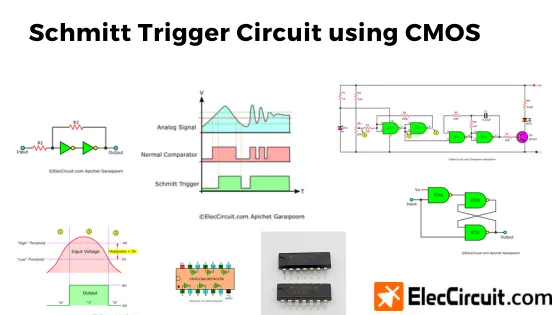
(1) At first, the output is in the “0” state. But as the input begins to rise from 0V, the moment that it surpasses the “high” threshold, the output switches to “1.” In this case, we suppose that the “high” threshold is set at 4V.
(2) Moving on, the input voltage starts to change and drops below the “high” threshold; nevertheless, the output remains “1.” However, as the input drops below the “low” threshold, the output switches back to “0.” The “low” threshold is set at 2V in this example.
(3) Lastly, as the input voltage decreases further, approaching 0V, the output remains “0.” For the output to switch to “1” again, the input voltage needs to exceed the 4V “high” threshold.
As opposed to a normal comparator, the thresholds for “high” and “low” of a Schmitt trigger are separated. The voltage difference between the two thresholds is referred to as the hysteresis; in this case, it is 2V. In summary, the Schmitt trigger requires the input voltage to either exceed the “high” threshold or fall below the “low” threshold for its output to switch state.
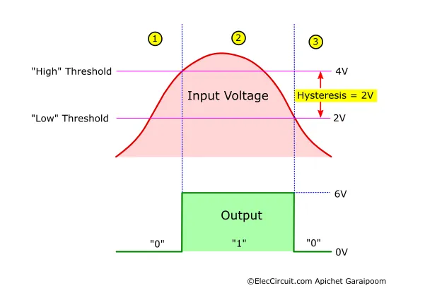
Schmitt Trigger Vs. Normal Comparator
The main difference between a Schmitt trigger circuit and a normal comparator circuit is that the former has two distinct comparing thresholds and the latter has only one. Let’s suppose that the input analog signal contains noises that may cause the voltage to fluctuate rapidly.
In a normal comparator circuit, as the signal level crosses the comparing threshold rapidly, the output also switches between “1” and “0” reactively, creating many small pulse-like digital signals. This barrage of pulse signals may cause digital circuits like flip-flops, counters, or light-sensitive switches to run into errors.
Whereas in a Schmitt trigger circuit, when the signal level reaches a certain threshold, the output changes and remains in that state even when the signal level decreases or increases from that threshold. The output only changes state when the signal level crosses another distinct threshold. The maximum voltage fluctuation of the input signal before the output state change is the hysteresis of a Schmitt trigger.
Popular Schmitt Trigger Integrated Circuit
There are many Schmitt trigger ICs out there; here are a few of them we often use:
For TTL chips, there are SN74LS13 NAND gates with Schmitt trigger inputs or SN74LS14N inverter gates, also with Schmitt trigger inputs.
For CMOS chips, there are MC14093 or CD4093, both of which are NAND gates, or MC14584, CD4584, and CD40106, which are inverter gates. All of these have Schmitt trigger inputs and function the same as regular inverter gates. The hysteresis for the CMOS chips also depends on the supply voltage.
Creating Schmitt Trigger from Normal Gates
In the case that we cannot find a Schmitt trigger integrated circuit or want to learn more about how it works logically, then you could also bring together NAND gates or NOT gates to create a Schmitt trigger.
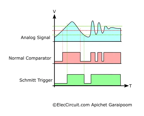
Using NOT Gates
The first way is to bring two NOT or inverter gates and connect them in series with each other, as shown below.
R1 and R2 will determine the hysteresis range. For instance, if the ratio of R2 to R1 is 10:1, the hysteresis will be about 5% of VDD. But if the ratio is 2:1, the hysteresis is as wide as 40% of VDD. This way is more suitable for CMOS-type chips; using TTL makes changing the hysteresis more difficult.
Using NAND Gates
Another way is to connect three NAND gates in the manner shown below.
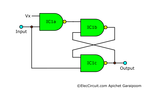
The hysteresis is determined by the VX voltage that goes into the first NAND gate. If the VX is 60% of VDD, the hysteresis will be about 10% of VDD. However, if we decrease the VX to 52% of VDD, the hysteresis increases to 30% of VDD.
Example Schmitt Trigger Circuits
Now let’s look at some of the simple digital circuits that utilize Schmitt trigger circuits. They may help us better understand a Schmitt trigger and how to use it.
Automatic LED Night Light Circuit
This circuit is an automatic LED night light using the CD4069 as a Schmitt trigger. As the name suggests, the LED will light up at night and turn off during the daytime. It helps save energy by turning off the light when it is unnecessary.
This circuit uses the LDR (light-dependent resistor or photoresistor) to detect the light level and then controls the LED accordingly. The LDR is a type of resistor that changes its resistance depending on the surrounding brightness. The higher the brightness, the lower its resistance; conversely, the lower the brightness, the higher its resistance.
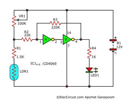
In the circuit, LDR1, together with R1 and VR1, functions as a voltage divider. When the surrounding brightness is high, the resistance of LDR1 decreases, causing the voltage across it and R1 to decrease as well. The IC1 interprets this lower voltage as a “low” state and outputs a “0,” meaning that the LED remains off.
On the other hand, when the brightness is low and the resistance and voltage of LDR1 increase, IC1 interprets it as a “high” state and outputs a “1”; as a result, the LED turns on.
However, if the surrounding brightness suddenly increases again, the voltage from the voltage divider may drift below a “high” state. This is where R2 and R3 come in; they convert the IC1’s inverter gate into a Schmitt trigger, meaning that the output would not switch to “0” immediately. In other words, R2 and R3 set the hysteresis for the IC1’s inverter gate.
Car Battery Voltage Monitor Circuit
As opposed to a normal voltage monitor circuit, we want a circuit that uses a blinking LED to alert us when the voltage of a 12V car battery decreases below a certain level. In addition, we want the LED to stop blinking when the battery is charged up to another higher level.
The battery voltage thresholds for an LED to start and stop blinking are different. Therefore, we need to use a Schmitt trigger circuit and set the hysteresis as the difference between the two threshold levels.
How it works
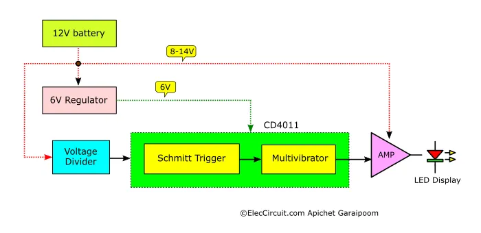
This circuit only requires a single MC14011 or CD4011 chip. We use IC1a and IC1b together as a Schmitt trigger circuit and use IC1c and IC1d as a multivibrator to cause a blinking effect for the alert LED.
The power supply for this circuit is from the battery it monitors. The voltage first passes through a voltage regulator comprising a 6V Zener diode (ZD1) to maintain a stable voltage supply for IC1. This ensures that the voltage that the Schmitt trigger receives will be 6V when the battery voltage is in the range of 8V to 14V and operates correctly.
At the input of the Schmitt trigger, there is a voltage divider consisting of R2 and VR1. They divide the voltage of the battery for the input while retaining the same proportion. When this voltage drops below a certain level, a Schmitt trigger immediately switches its output to “0.” The VR1 also adjusts the minimum voltage for the circuit to start working.
The hysteresis of the Schmitt trigger is the ratio of R4 and R3. In this circuit, we set the ratio of R4 and R3 at 10:1. Thus, the hysteresis is about 0.3-0.5 V, but if we want a wider hysteresis, we have to decrease the resistance of R4 or increase R3 to lower the ratio.
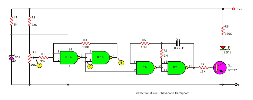
When the voltage at the input of the Schmitt trigger—the A point—drops below the determined level, the output—the B point—will be “0.”
However, the multivibrator IC1c and IC1d need to receive “1” at pin 9 to work. We thus use the voltage from the C point, which is the opposite of the B point, to control the multivibrator instead.
When the C point switches to “1,” the multivibrator works and sends an oscillating signal to the LED1 through a transistor Q1.
Setting
After charging the battery to a certain level, the C point switches to “0,” the multivibrator stops working, and LED1 turns off. Lastly, a transistor Q1 amplifies the current from the output of IC1d to be sufficient to drive an LED1.
Normally, a 12V car battery would require charging when its voltage drops to about 12.4V. Thus, we will start by supplying 12.4V to the circuit and then adjust the VR1 until the LED1 starts to blink. Then increase the supply voltage further until the LED stops; the voltage difference from 12.4V is the hysteresis.

Written by: Apichet Garaipoom
Like many others, I started electronics with curiosity and simple circuits. Over time, I’ve found joy in sharing what I’ve learned—and now, I get to build with my kids. It’s a journey, and I hope this site helps you enjoy yours.
Read more about me
Great, exact, and friendly! Like allways. Mandy thanks and greetings Fromm Germany
Hello,
We are delighted to hear that you found our article interesting. Please look forward to seeing more of our content in the future. We wish you all the best.