This project is a sound level meter circuit that easy and very cheap, can drive 9 LED display,The LB1409 is used as base of this circuit makes them has small size.
This our circuit is simple that is designed in a modern style. Which uses the LB1409-IC1 alone, but can drive LED up to 9 LEDs. So provides light beautiful than the old.
LB1409-IC is evolved from LB1405-IC, Which LED driver has a 5 LED, by improving provide ability to drive LEDs up to 9 LED, and can connect to use both measuring AC, DC.
Therefore, it may be used as a VU-meter circuit and signal meter. However, in Figure 1 shows the circuit inside IC.
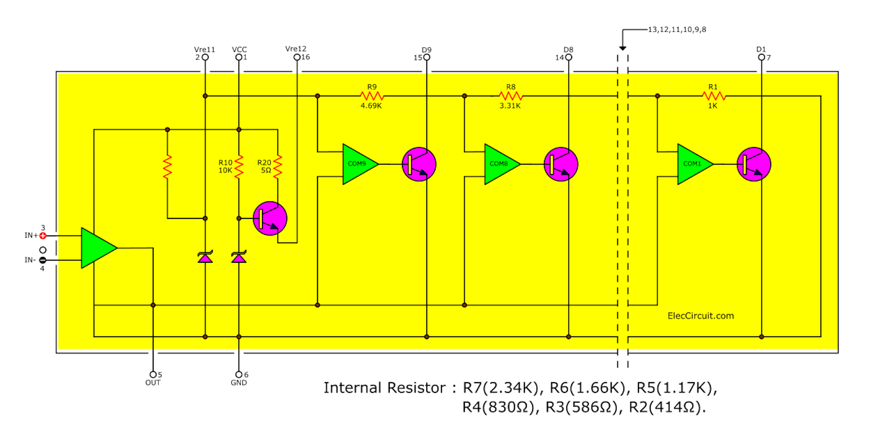
Figure 1 Show circuit inside LB1409-IC
Functions of LB1409
– Display: Bar shaped display of input level by means of 9 red, green LEDs.
– Comparator level: Following set up with 3 dB interval. -18dB,-15dB,-12dB,-9dB,-6dB,-3dB, 0dB, +3dB,+6dB.
– supply voltage: Recommended supply voltage range: 7V(Vccmin) to 16V. used at a lower supply voltage, use LB1409 of parallel drive type.
– Reference voltage: Pin Vref2 = 5V enabling constant current by means of the external transistor.
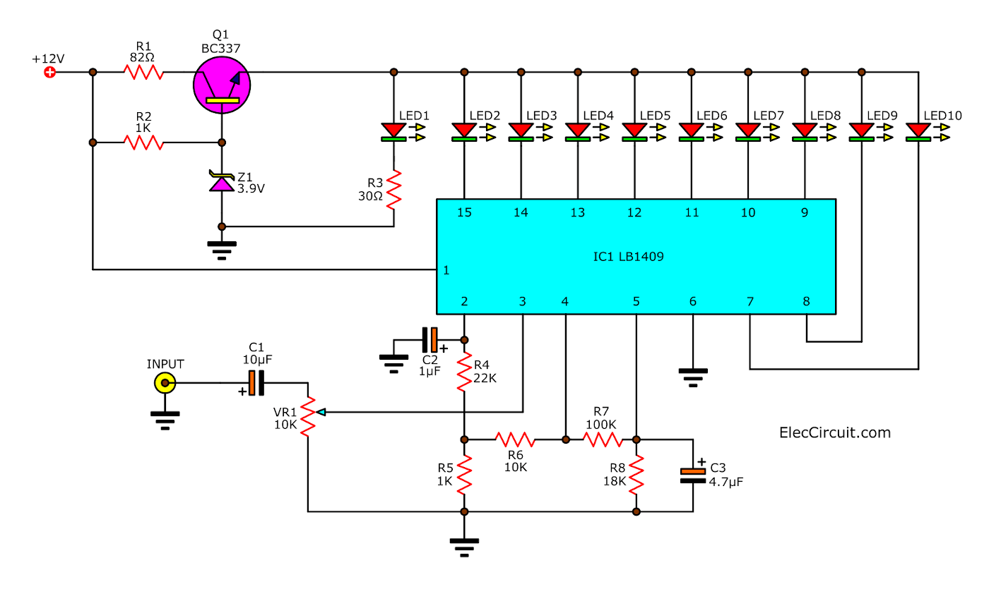
And in Figure 2 The simple VU signal meter circuit using LB1409.
How to build and uses
This project is easy to builds due to has a few parts. You can use PCB layout and all components layout
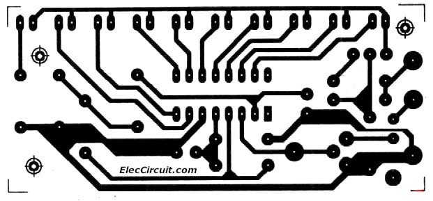
PCB layout on VU/Signal Meter
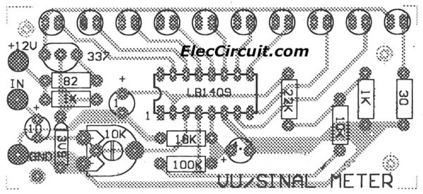
The component layout of VU/Signal Meter
It can be directly connected to measure the output signal of amplifier and use to replace the signal meter for a tuner. Or unless may use for measure a amplitude level of AC signal, such as the sound signal from tuner or CD player or MP3 player.
Thus may say that this circuit really well.
In application just adjust a VR1-potentiometer until LEDs glow as amount that you want, by conform to signal input.
In Figure 2 show connecting circuit to use as the signal meter circuits.
For you want to connect the LED of 10 pcs,may add LED1 that glow all time as show power on.
Related: This requires 12V Power supply.
The components List
IC1: LB1409, 9-element red-green LED level meter driver
Q1: BC337, 1A 80V NPN-transistors
0.25W Resistors, tolerance: 5%
R1: 82 ohms
R2: 3K
R3: 30 ohms
R4: 22K
R5: 1K
R6: 10K
R7: 100K
R8: 18K
C1, C3: 4.7uF 25V, Electrolytic
C2: 1uF 50V, Electrolytic
VR1: 10K, Potentiometer
ZD1: 3.9V, Zener Diode
Related Posts

I love electronics. I have been learning about them through creating simple electronic circuits or small projects. And now I am also having my children do the same. Nevertheless, I hope you found the experiences we shared on this site useful and fulfilling.
why all my led lights up..i used microphone as an input
Hi tbf,
Thanks for your question. I am glad that you have tried to create this project. I also want to build this project as well. (If have free time).
I want to help you.
You try to adjust VR1 to min. The LEDs should go out.
If it still lights up please circuit again.
I believe that you will check the equipment many times until it may be a headache. I’m sorry that it makes you difficult.