Let’s make 5-minutes Power Off Delay Timer Circuit. Because we should always save battery power. The easiest way is to turn on the light only when needed and turn it off when not. But in practice, we often forget to turn off the lights even when they are not needed.
My daughter has a small artistic corner that requires light from a 12V 3W LED light bulb. When used with a 12V 3Ah battery, it can be used continuously for about an hour.
But she only creates art for 30 minutes or less at a time.
She often forgot to turn off the lights, causing negative effects on the battery because the battery power is completely drained. making the battery deteriorate faster than it should.
My daughter said she wanted the system so that once the power switch is pressed, the LED will stay on for about 5 minutes and then turn off by itself. Then, if you want to continue using the light, press the switch again.
Or if you press it before the timer runs out. It will extend the light for another 5 minutes, adding to the remaining time.
For example, if three minutes pass since pressing the switch, there will be two minutes (2 min) left in the timer. But if you press the switch again during that time, it will add another five minutes. making the light stay on for another seven minutes (2+5 min) without having to wait for the LED to go off first.
And there should also be a reset button to reset the remaining time to 0 minutes or standby mode again.
With this system, we can save more electricity by solving the problem of forgetting to turn off the light and to help manage time for various activities, such as playing mobile games, brushing your teeth, etc.
How it works
First, let’s put the circuit concept from above into a more understandable block diagram.
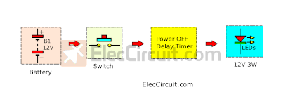
Now that we see what we will need for the circuit to work, let’s start with the main and most important part: the Power off Delay timer.
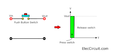
The idea that when you press the switch, Vout will appear for the time that you press and hold the switch is well known.
But we need to delay or further extend the time of Vout.
Designing power off delay timer
The simplest way is to use a capacitor. It stores energy and lets it out in a short period, with a larger capacitance one retaining more energy and letting it out in a longer period.
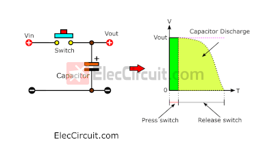
When we connect the capacitor across the output, then we push the switch and release it. The Vout (in the green graph) persists for a while and gradually decreases until it runs out. Because when we press the switch, the capacitor will be charged with voltage.
The next instant, we release the switch, discharging the voltage from the capacitor.
So we tried connecting the LED to the output. But the LED stays on for a short moment.
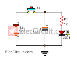
Then we swapped out the capacitor for a 1,000µF one, which made the LED stay on longer. But when used with a 12V 3W LED, the delay is quite short because this LED consumes much more current. So we would need the driver or controller for such a high current load.
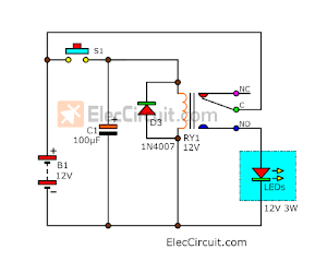
There are multiple components available to be used as a driver. But we usually choose a relay because it’s easy to use, similar to a normal switch. We simply enter a low current of about 20mA to 30mA into a relay coil, producing an electromagnetic field that pulls the switch contacts together.
As a result, a higher current from the 12V battery flows through it to the 12V 3W LED, lighting it up.
But the delay is still too short. This can be solved by changing the capacitor to a 2,200µF one or higher. But it is quite large, so we choose 100µF capacitor, but with an extra circuit to lengthen the delay instead.
According to the principle of the RC circuit time constant, we can determine the period from the formula: T = RxC
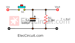
When we want the period value, T = 5 minutes or 300 seconds (5 x 60),
What value of resistors do we need?
R = T/C
= 300S/100µF
= 3MΩ
But we would have to use a 3.3MΩ 0.25W resistor instead.
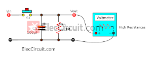
Then we test with a voltmeter, and the voltage drops to zero volts in 5 minutes, or it will discharge for about 300 seconds, as calculated above.
Because the voltmeter has a very high resistance resistor at its input, said resistor has no effect on the discharging of the capacitor.
Let’s analyze the problem together. When using the relay driver circuit above, the relay coil resistance is only below 600Ω. It has a great impact on the RC time constant circuit.
Delay Relay circuit using transistor
So, we add a transistor driver circuit to drive the relay coil, which consists of a transistor (Q1) and a resistor (R2). This will create more resistance to reduce the impact on the discharge of the capacitor.
But the delay is still less than 5 minutes. What else can we do?
If we were to keep this relay driver, how can we increase its input resistance or its input impedance?
Using the Buffer Circuit
We could add a buffer circuit to it. The buffer circuit has a very high input impedance (resistance).
There are many buffer circuits out there, but now we will use a CMOS digital IC: CD4093 Quad 2-Input NAND Schmitt Triggers.
Coverting NAND gate to buffer
The CD4093 internal structure consists of four NAND gates. But we only need two of them to create a buffer circuit.
We start with the buffer from two NOT gates or inverters that are connected in series.
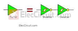
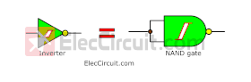
The inverter comes from the NAND gate with two of its input pins connected together.
And we will get the buffer from connecting two CD4093 NAND gates in series.
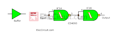
The buffer input has a very high impedance (more than 10 M of resistance), so it has no effect on capacitor discharging.
In addition, the Schmitt Triggers make this circuit more efficient. As the capacitor discharges, the voltage level continues to decrease. The Schmitt Trigger causes the output’s state to change to “0” immediately, causing the relay driver to cut off the LED.
It thus reduces a voltage spike or transient from the switch contact of the relay.
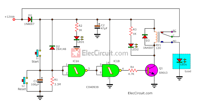
Next, we take each part and assemble them together into a complete Power Off Delay Timer Circuit circuit.
We have added a few more components to increase the efficiency of the circuit, consisting of:
- D1 prevents wrong polarity placement. When I was now about 11 years old, the same age as my daughter at the moment. I used to power the CD4093 in the wrong polarity, and within 3 seconds it was broken, so having a protection diode is a good thing.
- D2 protects against negative voltage that may be caused by capacitor discharging. It may damage our IC.
- C2 is a ripple filter capacitor.
- LED1 is the power-on indicator of this circuit.
- R2 limits a safe current for LED1.
- LED2 indicates the delay timer is working.
- R3 limits a safe current for LED2.
- D3 protects against negative spike voltage that may be caused by the relay coil. It may damage Q1 and others.
The disadvantage of this circuit
We can see that if S1 and S2 are pressed at the same time, there will be a short circuit. A large amount of battery current flows through D1. Be especially careful!
The way to prevent this problem is by skipping S2 (reset) entirely and adding an on/off switch to the battery instead.
The reason why I don’t put the on-off switch in the first place is that it happens to run out at the time of making. Also, this circuit consumes very little power anyway.
Improving this circuit with 3-position SPDT Toggle Switch
We can solve the above problem with an ON-OFF-ON, 3-position, 3-terminal SPDT toggle switch, as below.
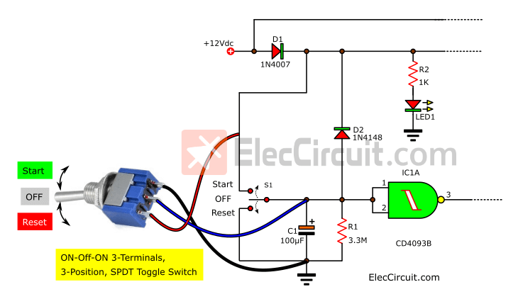
The switch lever is normally in the middle position (OFF) to close the circuit. But when the switch is moved to the Start position and then returned to the OFF position, it will start the circuit. But when we move the switch to the Reset position and then rock it back to the OFF position, it will reset the circuit again as above.
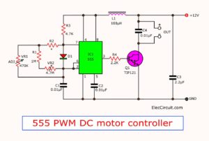
Learn: How to use 555 timer circuits
You may also like these timer circuits:
- 10 Second Fan ON delay
- The Basic Delay Timer Circuits
- Automatic timer switch
- Timer control 1-15 minutes
- Timer set for 30 minutes
- 5-30 minuts timer circuit using IC-555

Related Posts


I love electronics. I have been learning about them through creating simple electronic circuits or small projects. And now I am also having my children do the same. Nevertheless, I hope you found the experiences we shared on this site useful and fulfilling.
Hello,I check your blogs named “5 minute time delay circuit using CD4093 – ElecCircuit.com” on a regular basis.Your story-telling style is witty, keep doing what you’re doing! And you can look our website about proxy list.
Hi
There is a big error on this schematic !
Concerning IC 1 B :
-Input pins are 5 and 6
-Output is 4
Hello, dear friend!
Thanks for the correction.
We have already rewritten this article.
God bless you
Apichet&Kids
Clever. Great circuit.
Don Lancaster says, when using CMOS gates as inverters, use one pin as the input and tie the other inputs to the positive or negative rail, depending on whether you use a band or nor.
Why not use a 3 position toggle switch (DPDT) for S1 and S2? – then mechanically you will not be able to cause a short circuit as they are interlinked
Hi,
Thank you for your suggestion. your understanding is correct.
It is a really cool idea.
At first we will use another switch, SPDT Toggle Switch (on-off-on 3 position toggle switch).
It works better. But at the moment we do not have it so we use a simple push switch. 🙂
bonjour est il possible de remplacer le bouton poussoir par un mécanisme de reinitialisation automatique pour que le circuit puisse fonctionner de facon repetitive seul?
Paix à vous
Hi,
Thank you very much for visiting our website. I’m sorry If I misunderstand your meaning.
You want it to be when you press the reset button.
And then the circuit restarts automatically or not?. The concept is interesting.
We expect that we will design this circuits in the future.Hope you will follow us. 🙂