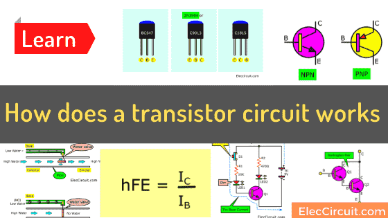
Let’s learn how the transistor circuit works. Although the transistor is a very old device. And, nowadays, we often choose to use IC instead. But the transistor still has an important role in general electronic circuits. Why? Because the transistor is large, durable, and can drive high currents.
And for many people getting used to using transistors in general circuits, me too.
How does a transistor work
Whether you are any reason. Let me explain to you how the transistor circuit works in a simple way. Also, I will learn it with you.
Are you ready?
The transistor is an active device. It amplifies. There are many types of transistors over 20,000 different types from hundreds of manufacturers.
Type of Transistor
We can put them into two types of standard transistors, NPN and PNP. Which they have different transistor symbols.
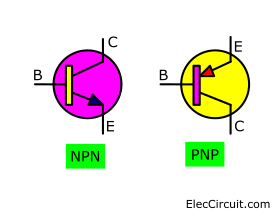
The character shows the class of semiconductor materials used to make the transistor.
Currently, the transistor used is mostly NPN type. Since it is made easy from silicon materials. So, most of this article, so mentioning the NPN-type transistor.
And if we are new to electronics. It is good to start with learning. About the use of transistors first.
The transistor pin consists of a base (B), collector (C), and emitter (E).
The word that calls this leg. Represents the function within the transistor. But it does not help you understand how to use transistors. Therefore, it only knows that it is a lead of transistor.
In addition to standard transistors (bipolar), there is the Fields Effect Transistor. They are often represented by acronyms FET. Symbols and properties are different. But have not yet discussed the details in this article.
Recommended: Transistors—make an amplifier or switching circuit
Equivalent Transistor
The type we will study is also called a small-signal transistor. We may call them a TO-92 model. Look at the Figure. We often use the transistor in the 3-number group.
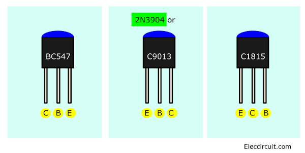
Which the legs are used differently. Should be careful when using.
- BC547: For NPN you can use BC546, BC547, BC549, BC550, etcs (Ic=0.1A to 0.5A). If you want higher current of Ic use BC337 (Ic= 0.8A). For PNP types, use BC556, BC557, BC558, BC559, BC560, etc. And higher current is BC327( Ic=0.8A)
- C9013 or S9013: For NPN you can use 2N3904. If you want a higher collector current(Ic) use C9013(Ic=0.8A) For PNP types, use 2N3906 and C9012 (higher current)
- 2N3904: For NPN (Ic= 0.1A)
- C1815: For NPN is 2SC1815, equivalents: C945, C829. For PNP is A561
These tiny transistors (TO-92) have a gain of at least 100 times or hFE = 100 min.
A similar list for MPS9682 is BC557. But the pinout is different. So, be careful. Check it first!
Look at commonly used Power Transistors below. We will learn the next.
Learn more: Knowing the necessary specs of the transistor
How transistor works like a water valve
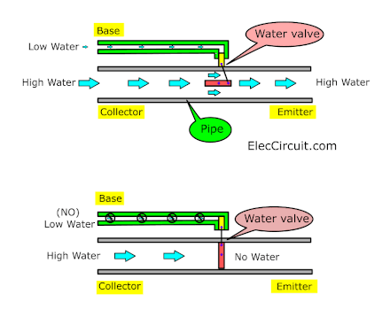
We compare transistors like water valves. We can control the high power of water input to output with low water.
- The origin of the water pipe(Input) is like the Collector.
- The end of the water pipe(Input) is like the Emitter.
- The control (small) pipe is like the Base.
First, The high water comes to the value of the input side. Then, the low water comes to the control value. It turns on the main value. Next, the high water can flow through the pipe to the output.
Second, in contrast, no low water in the control valve. It does not turn the valve to control the high water. So, no water to the output.
Learn basic transistor current
What is more? we will learn the current in a basic transistor circuit.
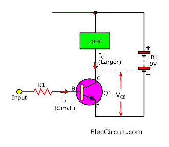
Look at Figure. The NPN transistor is in a simple circuit.
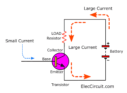
When we feed a small current to the base of the transistor. And then, a large current flows through the load to the collector-emitter leads.
We often called The load at the collector leads to the load resistor. Sometimes the load is a speaker.
I’m worried about how you understand simple transistors. In the past, I had difficulty understanding it. Read the text many times but do not understand it.
Basic working range
In general, we can divide the working range of the transistor into 3 ranges:
1. Cut off ( transistor stop).
No current, both base current (IB) and collector (IC) that flows through the transistor. But there will be some leakage currents, very low.
2. Saturated range.
There is electricity flowing through the transistor fully until it is saturated. And the current will not increase any more than this. Which we can limit this current with the connection of the resistors.
3. The active range
This is the period that the transistor operates or conducts current. By driving the collector current (IC) proportional to the base current (IB).
So, when using the transistor audio amplifier, the circuit works in the active phase.
Do you understand?
Experiment with a basic transistor circuit
In addition, I understand transistors systematically through experimentation. You maybe like me. Let’s start the experiment with a Simple current transistor circuit.
Look:
Simple current transistor circuit
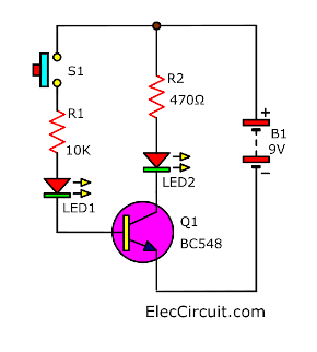
This is a simple circuit. Which we use to test the current flowing through the transistor. In this circuit, we use the red LEDs size 0.5 mm. And, NPN transistors with low power (such as BC108, BC182, or BC548).
Here is step by step a process of transistor circuit works.
The little base current controls the high collector current.
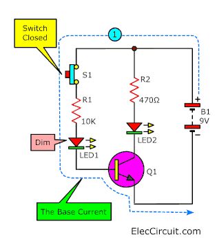
The S1 is switched closed. The current flows through R1, and LED1 to the base of a transistor.
It is the base currency. While LED1 dims up, too.
Then, the transistor will amplify the low current so that the current flows through the collector (C) to the emitter (E).
This collector current is high enough to make LED C very bright.
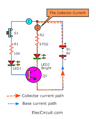
When the S1-switch opened. There are no base current flows. So, the transistor will cut off the collector current. Both LEDs will go out.
Often we use the transistor to amplify the current and switches.
The arrangement with emitter (E) in the base current and in the collector current. We called emitter common mode. The transistor circuit works like this and is used extensively. So, We should learn it first.
Working model and structure of NPN transistor
I feel frustrated because I cannot easily explain to you understand about the internal structure of the NPN transistor.
However, I will try to compare it with the diode and variable resistor. It may help you understand more easily.
Look at below.
Here is step by step a process.
- The base-emitter joint is like a diode.
- The base current IB flows only when the VBE voltage between the base-emitter is 0.7V or more.
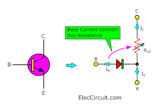
- The tiny base current (IB) controls the high collector currents.
- IC = hFE × IB (unless full active and saturated transistor)
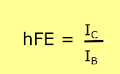
- The hFE is the current amplify gain (In DC current gain). The normal value for hFE is 100 (there is no unit because it is the ratio).
- The resistance between The collector-emitter (RCE) is controlled by the base current (IB) by:
- IB = 0 RCE = infinite value. Transistor (off)
- Less IB, RCE lower, the transistor turns on only partially
- IB added. RCE = 0. The transistor runs (on) fully (saturated)
Additional Notes:
- It is necessary to connect a series resistor to the base. To limit the IB base current and prevent damage to the transistor.
- The transistor has the highest collector current rate of IC.
- The hFE current gain can have different values. Even though it is the same type.
- The transistor that is fully connected (on) (when RCE = 0) is called saturated.
- When the transistor is saturated The emitter-collector voltage VCE is reduced to 0V.
- And the transistor is saturated, and the collector current IC is determined by the voltage, the supply, and the external resistance in the collector circuit.
Not related to the transistor current gain.
For this reason, the ratio of IC / IB for saturated transistors is less than the hFE current gain. - The emitter current is IE = IC + IB, but the IC is much larger than IB.
Learn more about transistor circuits HERE
Darlington Transistor pair
The Darlington transistor or Darlington pair is two bipolar transistors connected together as shown in the picture below.
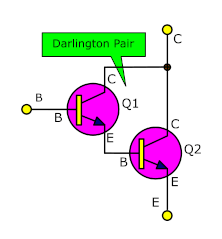
Why did it call Darlington transistor? – Because this configuration was invented by Sidney Darlington at Bell Labs in 1953. With this configuration, we are able to achieve a higher gain than a normal transistor. It also can be integrated inside an IC such as ULN2003
Most of the time, we prefer to use it in normal transistor circuit form than IC. Each circuit may or may not contain more than two transistors.
It causes the current amplified with the first to be amplified with the second transistor.
The current gain is equal to the gain of Each of them multiplied together:
The current gain of the Darlington pair hFE = hFE1 × hFE2
(hFE1 and hFE2 are the gain of each transistor).
For this reason, the Darlington pair has a very high current gain, such as 10000. Therefore, we use only a small base current to allow the Darlington pair to switch.
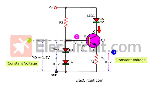
The Darlington pairs instead of a single transistor with a very high current gain. Also has three legs (B, C, and E), which is equivalent to the legs of a single transistor.
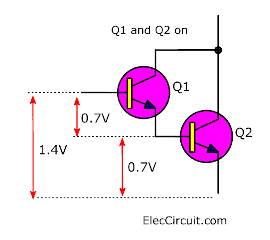
We can use the Darlington pair works well.
By putting the voltage 0.7V between the base-emitter ( VBE) of both transistors in series internal. So they require a voltage of 1.4V to turn on.
The experiment on the touch switch circuit
The transistor circuit works as the Darlington pair is quite sensitive to the small currents that flow through our skin. Thus, able to be used to make a touch switch circuit as shown in the diagram.
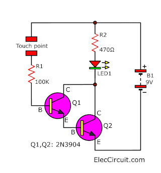
For this circuit, use two low-power general-purpose transistors.
When we touch it, the LED is illuminated.
The 100K resistor is used to limit the base current.
These Darlington transistor circuits are used in many kinds of circuits.
- Audio amplifiers
- Water Alam: it will measure a very small current that goes through the water.
- A non-contact AC voltage detector: It is a high gain amplifier using 3 transistors.
- A touch switch: If we connect it to a piece of metal, we can make a touch-sensitive button.
Check out these related articles(using Darlington), too:
- 555 PWM LED dimmer circuit diagram
- High impedance small amplifier circuits
- non-contact voltage tester using transistors
Using a transistor as a switch
When we use the transistor as a switch. It will turn off (OFF) or turn on (ON).
In the (ON) voltage, the VCE across the transistor is almost zero volts. and we call it a saturated transistor. Because it cannot have more collector current (IC).
Look at the simple switching transistor circuit works below.
The output device that is switched by this transistor is called a load
The power generated in the switch transistor is very low:
- In the OFF state: power = IC × VCE, but IC = 0, so power is zero.
- In the ON state: power = IC × VCE, but VCE = 0 (most), so the power is very low.
This means that the transistor used will not become hot. So, do not consider the maximum power rate.
But the important rate in the switching circuit is the maximum collector current IC (max). And, the minimum current gain hFE (min).
The voltage of the transistor must not be taken into account. Except, if used with a power supply higher than 15V.
Recommended: Experiment with transistor as switch
The Protected Diode
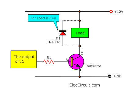
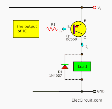
If the load is a Motor, Relay or Solenoid (or other devices that is a coil). We will connect a diode across the load. To protect the transistor circuit works (and IC) damaged during cut off the load.
Look at the circuit diagram.
In the diagram showing connecting reverse biased the diode. Which normally does not conduct currents.
It will conduct the current only when the load is cut off.
At that time, the current that collects energy in the coil will try to flow through the coil.
And, Because the transistor is cut-off status. So, the current flows through the diode instead.
If It no diode, the current will cannot flow. This coil will produce a high spike voltage. It is dangerous and tries to flow.
Read also: Switching transistor circuit in the digital circuits
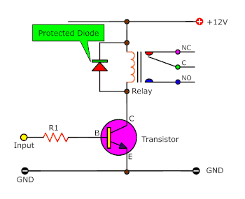
When should we use the relay
We cannot use the transistor to switch AC voltage or the high voltage (such as AC main). And it does not suitable to switch too high current (> 5A). In this case we need to use the relay.
But we also need to use a low power transistor to drive the current to the coil of the relay.
Benefits of relays:
- The relay can switch AC and DC power, the transistor can switch only DC power.
- It can switch on the high-voltage power, the transistor can not.
- Relays are a better option for switching to high-current (> 5A).
- The relay can switch Multiple contacts at the same time.
Disadvantages of relays:
- The relay is too big compared to the transistor in the small current switch.
- The relay cannot switch with speed, the transistor can switch many times per second.
- Relays require more power Look at the current that flows through the coil.
- Relays require more current than the IC can drive. So we need to use a low-power transistor to switch the relay coil current.
Credit: https://electronicsclub.info Thanks a lot. This content makes me easier to understand.
Connecting the transistor with the output from the IC
Most IC outputs cannot supply a lot of currents. So, it is necessary to use a transistor. To switch currents that are high enough for the output devices. For example, light bulbs, motors, and relays, etc.
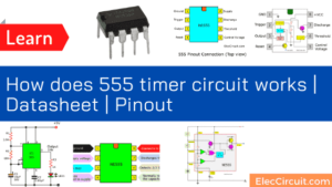
Except for the timer 555 IC, it can normally supply a current of up to 200mA.
It is high enough for the output devices that require a small current. Like the small lamp, buzzer, or relay. Without the help of a transistor.
Look at the basic circuit. Connect the transistor to the IC’s output.
Resistor R1 is intended to limit the current that flows into the base of the transistor. And prevent damage.
However, R1 must be low enough to ensure that The transistor is saturated, preventing overheating.
This is important if the switch transistor with a high current (> 100mA). The safest way, the base current (IB) must be 5 times higher than the current that makes the transistor saturated.
Do you understand? Read more you will feel more clear.
Choosing the right NPN transistor
The circuit diagram shows the connection of the NPN transistor. This circuit will switch to load when the output from IC is high (+ V).
On the other hand, if you want to continue loading when the output from IC is low (0V) Look at the circuit for the PNP transistor below.
The steps below explain how to select a suitable switching transistor.
- The maximum collector current (IC max) of the transistor have to more than the load current.
We can find the load current (LC) = Voltage supply (VS) / the resistance of the load. or
For example, we use the light bulb 12V 3W. It uses the current
= 1W / 12V = 0.083A. So we use IC max more than 0.1A or 100mA.
- The minimum gain current, hFE (min) of the transistor, must be at least 5 times the load current IC divided by the maximum output current of the IC (chip).
- Calculate the approximate value for the base resistor:
R1 = 0.2 × RL × hFE or
R1 = (Vs × hFE) (5 × IC)
Choosing the right PNP transistor
Look at the Circuit diagram showing the connection of PNP transistor.
This circuit will switch towards the load when the IC output is low (0V).
The procedure for choosing a suitable PNP transistor is similar to choosing an NPN transistor described above.
In addition, we are able to utilize transistors in many ways. Learn more:
- Using a switching transistor with a sensor
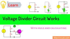
- Learn voltage divider circuit
- Inverter Transistor (NOT Gate)
…
10 Example transistor circuit
Read the principle, you are probably starting to understand. Next, let’s take a look at an example transistor circuit. Hope this is helpful to you.
1# Simple intercom circuit
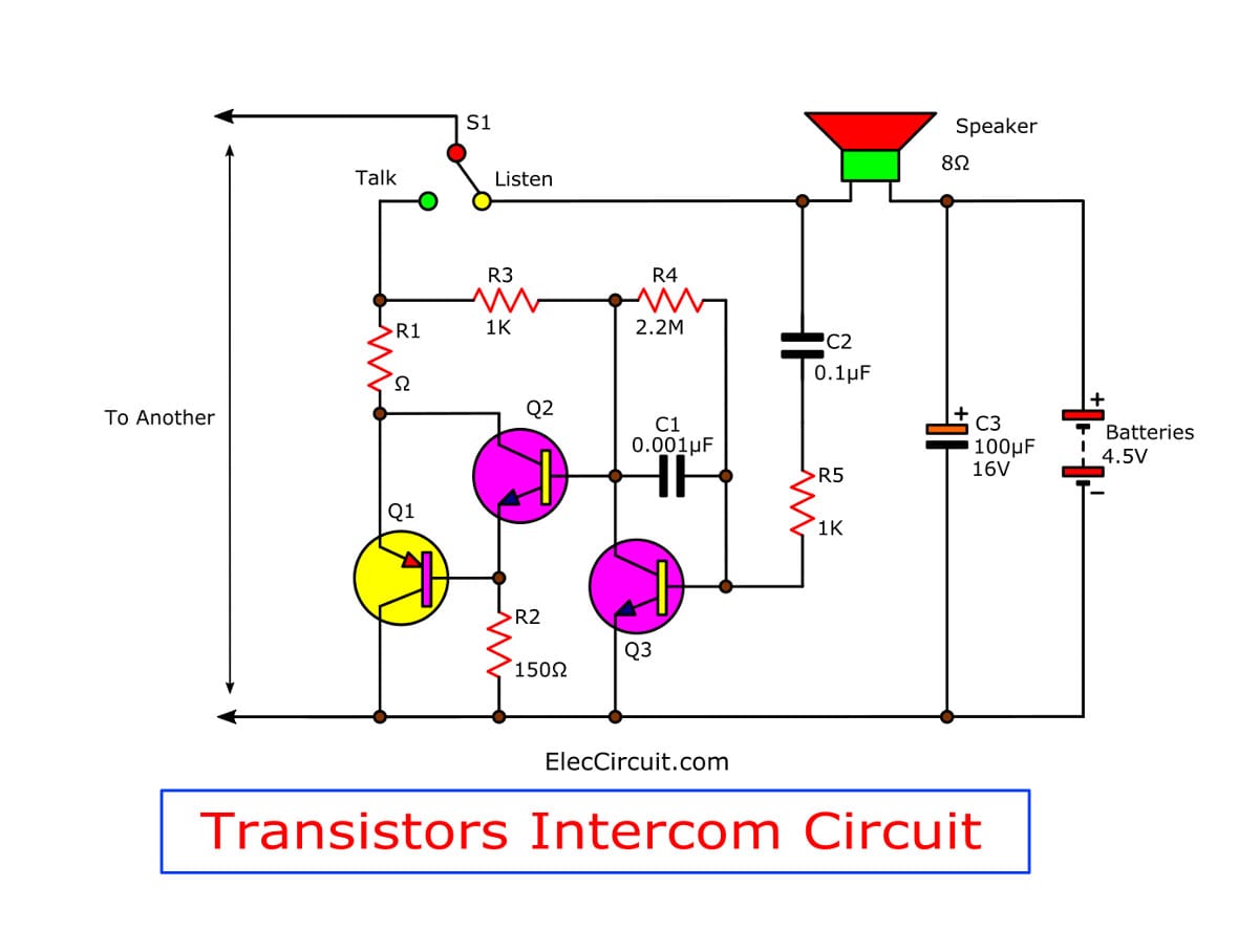
See a simple intercom circuit using transistors and a few parts. So easy to build and cheaper than ICs. For a small home and learning. Read more
2# 4 transistor audio amplifier circuit
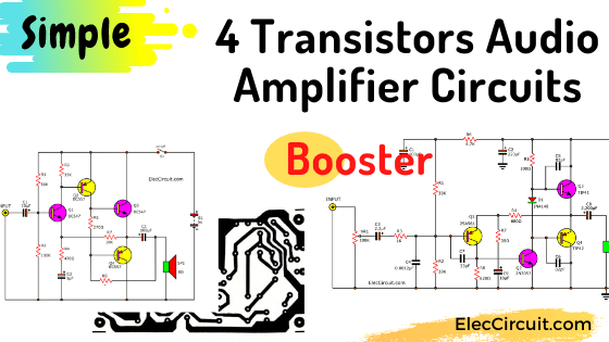
This is a 4 transistor audio amplifier circuit. Which is a 4-transistors complementary push-pull amplifier, that shows the basics of audio amplifier design. Read more
3# Simple transistor | police | ambulance Siren (audio alarm) circuits
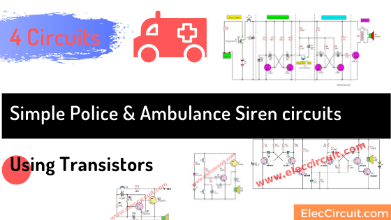
I would like to introduce the simple and economical simple Siren circuits. It is suitable for beginners. My son will gradually build this circuit onto the PCB layout.
4# Constant current circuit using transistors
Here is a constant current circuit using transistors. Because the Ni-HM battery should only be charged with a constant current. Our friends need it. Also, I and my daughter are interested in learning/trying out this circuit.
5# Small High Volts shock using transistor
This is a small high volts shock circuit, pressure from the low current. It is perfect for fun play. In circuit has a few components just two small NPN transistors, 2 resistors, and a transformer. So easy to build and cheap!
6# Simple 12V transistor switching power supply
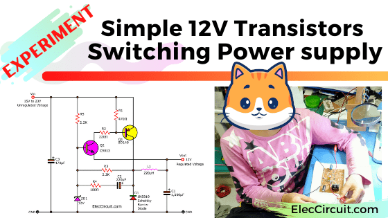
Can we build a switching power supply with 2 transistors? Yes, we can! Let’s experiment with a simple 12V switching power supply circuit using transistors.
7# Basic H-bridge motor driver circuit using bipolar transistor
A DC motor controller has many forms. I am going to suggest you learn an h-bridge motor driver circuit. So what? It is easy to do with a transistor or MOSFET drivers. And they are high performance, too.
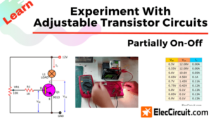
Read next: Experiment with adjustable transistor circuits partially on-off
Download This
All full-size images of this post as PDF are in Ebook. Thanks, your support. 🙂
Here are a few related posts you might want to read:
- Simple audio alarm circuit using transistors
- 4 transistor audio amplifier circuit
- Transistor Variable power supply 1A, 0-30V with PCB
Related Posts

I love electronics. I have been learning about them through creating simple electronic circuits or small projects. And now I am also having my children do the same. Nevertheless, I hope you found the experiences we shared on this site useful and fulfilling.
This Was Very Well Explained …………..THANK YOU!!!!
Hello Rick Hodgson,
Thanks for your feedback.
i will play touch switch circuit. easy transistor circuits,,:-)
Thank you so much. No other ‘explanation’ mentioned that there had to be another power source for the base, which I knew had to be the case.