This is a simple electronic drum circuit. Do you like playing music? Currently, electronic drums are popular. And we are the electronic inventors. I would like to present an electronic drum circuit. Our happiness is learning to create it. It can be applied to the various sound effects and many others.
Ready to get started?
How it works
First, we will explain the main idea briefly.
Look:
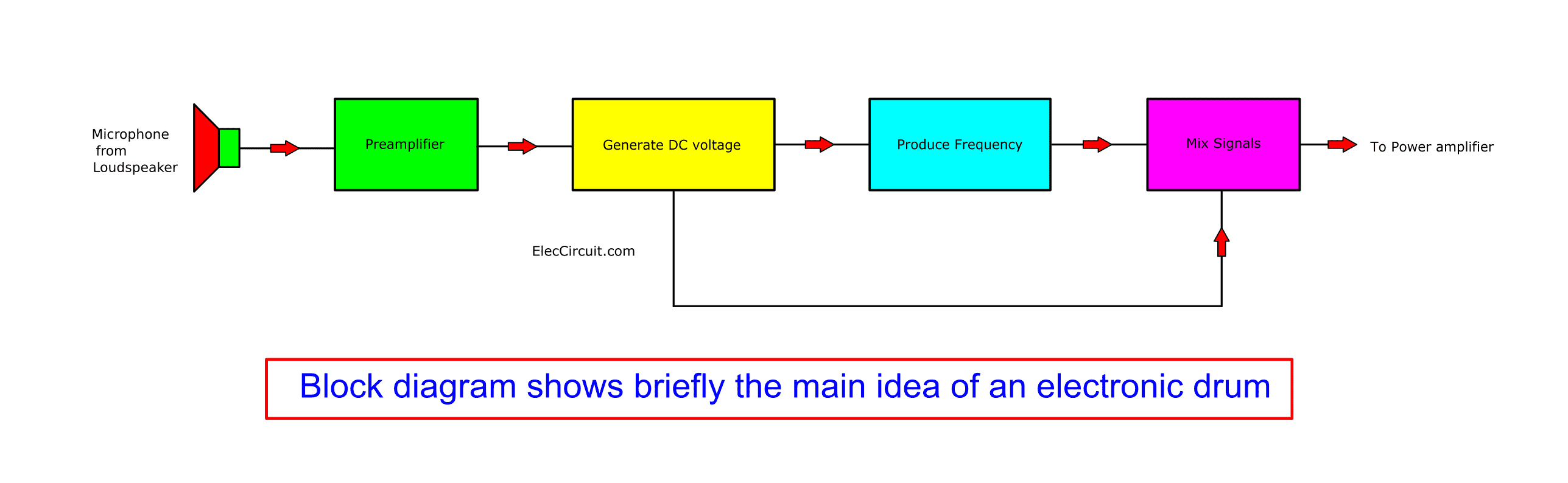
Block diagram shows briefly the main idea of an electronic drum.
Here is a step-by-step process.
- We use a loudspeaker instead of a Microphone. Knock on the front of the speaker. Make the speaker cone to vibrate, causing a small electrical signal.
- Then, amplify this signal to more higher.
- Convert to DC voltage.
- To control the production of frequency circuit.
- And, Mix this frequencies signal and DC voltage from the beginning.
- Last, send an output signal to a power amplifier.
You probably started to see the picture.
What is more?
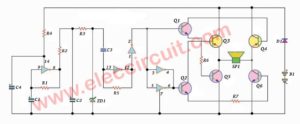
Let’s look at how the circuit works. As shown the circuit below is a complete circuit.
Sensitivity control
Here is the first section. Step working:
- Tap a speaker to make a little electrical signal, by knocking.
- Via C1 and VR1, to the Preamplifier into pin 3 of IC1.
- Adjust VR1 to controls level signal, called “sensitivity control”.
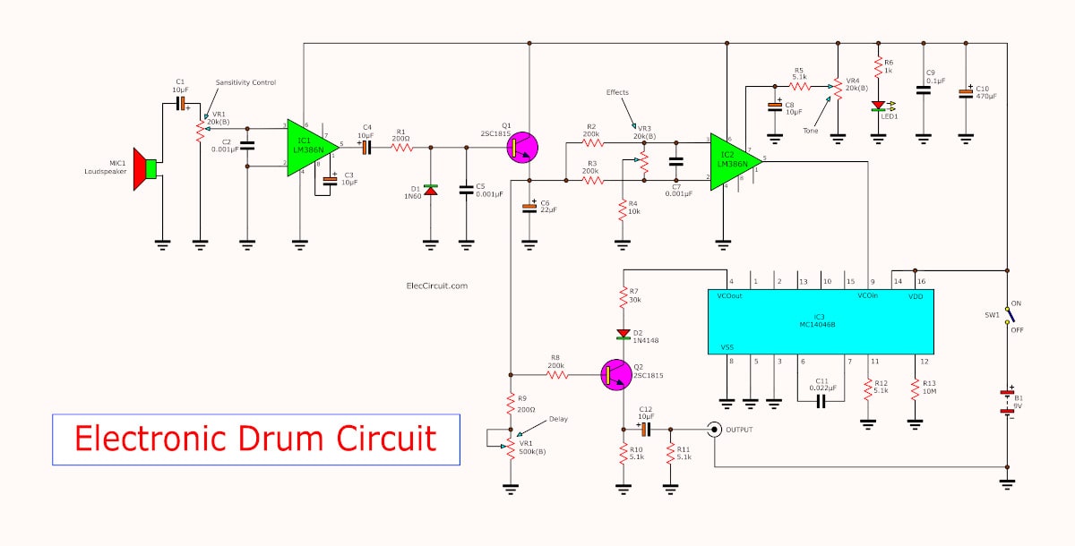
Although, we will knock lightly or forcefully. The circuit can recognize by adjusting this.
For example:
Tapping too heavy makes sound distortion, So, need to reduce the sensitivity down.
But if we gently tapped, low signal out. We can rotate VR1 to let a signal through well.
Next, the output signal of IC1 to convert into a DC voltage before.
By using D1 and C5 to more smooth DC. To control working in the frequency generators section next. Pass Q1 to increase a signal before.
Effects control
Some signals will pass IC2 to generate a frequency. And, adjust VR3 to control a fantastical sound from IC2.
Tone controller
Also, VR4 control the signal of IC2.
Then, that frequencies get in pin 9 of IC3. The IC3 is tone generator gives bass and treble. That signal comes out of pin 4 to mix signal from Q1 to Q2 first.
Then, output at pin E of Q2 via C12 to an input of power amplifier by RCA Jack.
Delay control
Adjust VR2 to control time delay, Sound was long or short.
How to build
You can assemble this project on the Universal PCB Board easily and fast.
If you want a PCB layout please email me.
Here is a step to build:
We put the correct resistor, Always read the resistance value and location. Well, that should make it horizontal or vertical.
Then, put the diode in its place correctly and successfully.
Put all the IC sockets on the PCB. What should be careful when inserting the pins of the socket. not folded pin and in the correct way.
And importantly, check the lead of transistors and All Electrolytic capacitors. We should also check the polarity of it, right before soldering.
The equipment outside of the PCB, as LED1 is connected to a cord circuit. If you should have two colors, black and red are connected to Pin A and K of LED1.
The speaker also to the red line in the positive and the black to the negative.
Then connect the power cable from the 9-volt battery via a switch on/off to the circuit before.
Later to a variable resistor value, the exact location, and values
And the cable length should be about 20 cm in each line, The JACK – RCA mono-to-mono cable shield is about 20 cm long.
Components List
0.5W Resistors, tolerance: 5%
R1, R9: 220Ω
R2, R3, R8: 200K
R4: 10K
R5, R10, R11, R12: 5.1K
R6: 1K
R7: 30K
R13: 10M
Q1, Q2: C1815 or C2001, 0.2A 50V, NPN transistor
IC1, IC2: LM386
IC3: MC14046, CD4046
D1: 1N60 Diode
D2: 1N4148, 75V 150mA, Silicon Diode
Electrolytic Capacitors
C1, C3, C4, C8, C12: 10µF 25V
C6: 22µF 25V
C10: 470µF 16V
Mylar Capacitor
C2, C7: 0.001µF 50V
C11: 0.022µF 50V
Ceramic Capacitors
C5: 0.001µF 50V
C9: 0.1µF 50V

Cr: Photo by RockJam
You may also like these:
- Simple train whistle circuit using NE556
- Video amplifier splitter using transistor
- Simple speaker delay circuit
- Tempo tap circuit using IC-CD4011
- 3 Sawtooth wave generator circuits
Testing and using
If you finished the building project. Your friends are waiting for a great dram sound.
Let’s set and test it:
Connect this circuit to the amplifier first.
Turn the variable resistor in the center, and volume down the amplifier.
Start to tap a speaker of the electronic drum. This project we use the speaker as a microphone. So, do not too heavy.
Adjust VR1 to control sensitivity in enough position.
Rotate VR2 to adjust the delay time, long or short time.
VR3 is used to adjust the sound weird. The middle position sound is normal but when rotated to the left or right, it will Sounding strange to mix with it.
– VR4 tone adjustment function to adjust the treble and the bass tone and adjusted according to your preference.
If you adjusted the results to explore the power cord attached to it or not. Or cable might be loose.
But if the no matter, it shall be as the test is finished and will be deployed as needed.
For implementation, depending on your objectives, the tapping noise as the suspension noise. Which helps relaxation or some people might like the music. It helps blend the sound of your music.
Enjoy with the project.

Related Posts

I love electronics. I have been learning about them through creating simple electronic circuits or small projects. And now I am also having my children do the same. Nevertheless, I hope you found the experiences we shared on this site useful and fulfilling.
hi please could u send me a list of components I need to do this via email