If you need to use a dual power supply. But you only have a single supply. So, you should build a power supply splitter circuit like this.
Often the many op-amps have this problem. They need a split supply. The output terminal has positive, negative, and ground. But most power supplies have only a single output (positive and negative). So, you cannot use them to power op-amp circuits.
Do not worry about this problem. You can just build the power supply like this. It will change the input voltage into the dual rail.
How Power Supply Splitter works
The main idea, it splits input voltage in half, two equal output. Which it has a ground, is midway between the positive and negative supply voltages.
The ground has to be a regulated voltage. And it powers a suitable current to load.
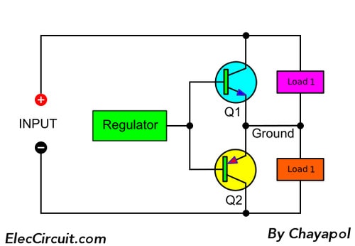
Figure 1 block diagram shows special two-way voltage regulator for load 1 and Load 2.
The regulator controls Transistor Q1 and Q2. Then the ground is a regulated voltage. It holds a fixed voltage between the + and – terminal.
If Load 1 and Load 2 uses equal currents. And, the voltage across them is still halfway. So the regulator do not change.
If the currents of 2 loads are different. Then, either Q1 or Q2 will conduct extra current to make up the difference.
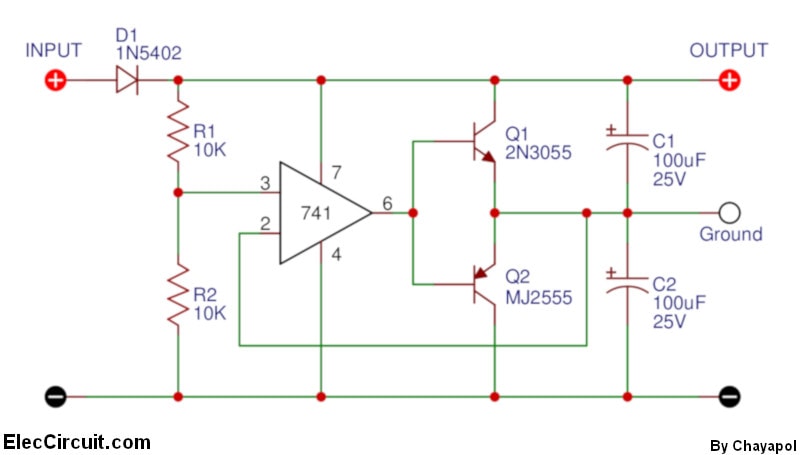
Figure 2 Shows the circuit. R1 and R2 divide the input voltage.
An OP-AMP-IC1 produces a regulated voltage at the “ground” output terminal. Then, either Q1 or Q2 conduct as necessary.
Both capacitors C1 and C2 keep the output voltage when the load changes suddenly.
Diode D1 protects the reversed polarity of the main power supply.
The turn-on voltages of Q1 and Q2 are 1.2 volts. So this may be a problem, dead zone. The output of IC1 must cross in order the catch up with an unbalanced load.
But this problem is little for IC1. It can cross the dead zone very fast.
In real testing. This circuit has a good regulator to power the OP-AMP circuits. And also other loads such as buzzers and flashing light bulbs.
Read also: 7805 Voltage Regulator
Parts List for the power-supply splitter
Semiconductors
IC1-LM741 operational amplifier,
Q1-2N3055 100V, 15A, NPN transistor
Q2-MJ2955 100V, 15A, PNP transistor
D1— 1N5402 (3A,50-PIV rectifier diode)
Additional parts and materials
R1, R2— 10K, 1/4 watt, 5% resistor
C1,C2—100uF, 25V, electrolytic capacitor
Enclosure, binding posts, circuit board, solder, wire, the optional heat sink for Q1 and Q2, etc.
Not only that You can look other power supplies: Learn more
Construction
Because there are so few components, a printed-circuit board is not necessary.
We can assemble the smaller components (D1, R1, R2, and U1) on a universal PCB Board.
Should put capacitors C1 and C2 close the output terminals.
The cheap 741 IC is the best OP-AMP. If we use higher performance OP-AMPS such as the TL081. It cannot improve the performance of the circuit.
How to use its
You can use the splitter with fixed- or adjustable voltage power supplies. They range from 8 to 30 volts. Make sure, it is an isolated power supply.
This splitter can handle at least 250 mA at a 30-volt input.
The specified transistors and proper heat sink, this splitter can handle many amps.
If you do not have 2N3055 and MJ2955. But you have TIP41 and TIP42 or a smaller sizes.
Not only that You can look other power supplies: Learn more

Related Posts

I love electronics. I have been learning about them through creating simple electronic circuits or small projects. And now I am also having my children do the same. Nevertheless, I hope you found the experiences we shared on this site useful and fulfilling.
I have dual out put DC regulated adapter 30V having two + and two – out put, can I use it to power dual power amplifier that requires one + and one – and GND?
Hi Friend,
Yes, the input voltage is 30V max. Then, the output is +15V GND -15V.
Thanks
Hi, the regulated adapter already have dual DC out put of 30 V, two plus and two minus, can I connects one plus to one negative to make it as GND?
What happens if I use more than 30v input for this circuit? do I need different circuit to get higher than 30v
Hi Friend
I feel bad that I don’t quite understand your message. I’m sorry. If I misunderstood. I use Google translate.
No, this circuit cannot use for more voltage than 30V input. Because of IC1 and transistors.
But we may modify for other circuits.
If I have more time. I want to help you test other circuit ideas.
But I have been busy. I am going to build a new home in the garden.
Have a great day.
Apichet
Can I replace D1 IN5402 with IN5404 or IN5408 diode?
Yes, You can.
I build this project and it works well with my dual input amplifier, except one amplifier that requires 12-18v dual input, it did not work, not sure why, though this amplifier can work on two 9v batteries connected in serial and I used the the (+ and -) as GND.
Hi, my friend,
Thanks for your feedback. Is it worked? It is good news. How many input power supply voltage?
I am quite not sure about your text, my English is poor and my brain is slow. LoL…
Your Some circuit does not work. Is it a preamplifier circuit? It requires 12V to 18V Dual voltage (+ GND -)
Yes, you may try x2 9-volts batteries in series.
I hope your circuit worked well.
Thanks