Imagine the important electronics circuit you need working all time. But sometimes loses power, it runs out of energy for working as a power outage. We need to use a UPS circuit UPS (Uninterruptible Power Supply) circuit Diagram diagram.
Some call the emergency backup battery systems. It can be applied to many applications. When the power goes, the battery can provide backup power automatically.
We have a lot of ways to do it. But I love a simple ways that cheap and easy. You can build it easy with normal components in your store.
Small 6V UPS circuit (7V Backup)
If you want 5V to 7V power supply at 0.5A current. This circuit is a good choice for you. Without IC and easy too.
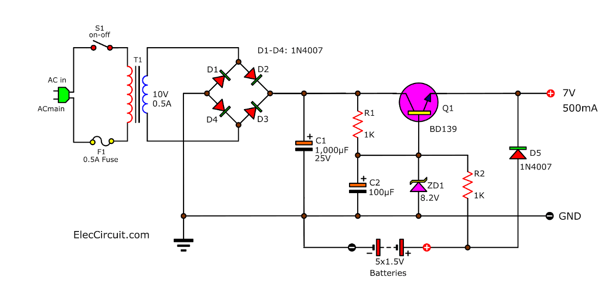
This system consists of a transformer, a bridge rectifier, and an electrolytic capacitor. And there is a Zener diode for controller the output power transistor(BD135 NPN) of this circuit.
And It will deliver a constant voltage of 7 volts. If you use a normal AA 1.5V battery. Read next…
How it works
Look at the circuit below.
We connect the Backup battery 7.5V (AA 1.5Vx5) with D2 in series, and both across the output terminal. The voltage drop across D2 serves to reduce the voltage level of the power supply down to about 7V (6.8V).
Also: 8 ways how to converts 12V to 6V
Small Uninterruptible Power Supply UPS Circuit
When use this with the AC main. The R2 will via some current to charge the dry batteries or rechargeable battery. At the same time, it will prevent over-charging, too.
Not just only that R2 also simply keep the current flowing from the battery not runs out, while using the full functionality of the AC main.
This resistance can be calculated, by dividing the voltage between the Zener diode and battery, with value battery current for safety.
Shopping list
Q1: BD139, 1.5A 100V NPN transistor
R1, R2: 1K, 0.5W Resistors
C1: 1,000μF 25V, electrolytic type.
C2: 100μF 25V, electrolytic type.
ZD1: Zener diode 8.2 volt 0.5 watts
D1-D5: 1N4007, 1000V 1A Diode
T1: Transformer 0.5A 10V
B1: AA battery 1.5V x 5 pcs
How it builds
We use the component very small. So, it is not necessary to make PCB (printed circuit boards). And, can all soldering electronics components (except for transformer) on the small Perforated PCB.
The batteries list:
- Normal AA battery (1.5Vx5 = 7.5V)
- NiMH battery (1.2Vx5 = 6V)
- 6V lead-acid battery.
It works great as well. This circuit can supply enough current to 500mA circuit applications. For example, a small digital clock, a small emergency lighting system, and more.
Read related
- 3 Simple Emergency Light circuit
- Power Bank Mobile Charger circuit
- 7805 and 7905 Dual adjustable power supply
Above circuit, we may not like it and it works not well. low current and quite hard to build.
Let’s try to use IC better, below!
6V Backup Battery Regulator Using 7805
These simple and cheap 6-volt power supply circuits with a 6V backup battery system or 6V UPS circuit diagram.
How it works
First, the AC power 220V is entered to through input of transformer-T1 to reduce voltage as 9VAC. Then, the wire connected to four diode D1-D4 as bridge rectifier became to 11VDC.
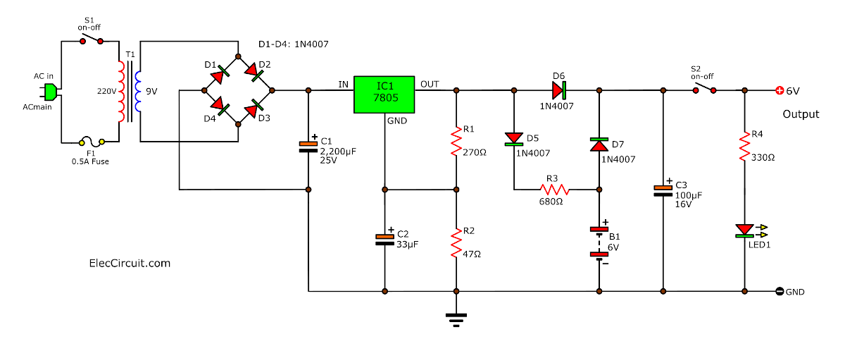
Next, the current is filtered into DC voltage that low ripple output. After that, the voltage is regulated to a 6VDC constant voltage by IC-KA7805( IC-7805 type).
In normal, we use it for 5 volts only. But now we add two resistors to the determined output voltage is 6.7 volts and passed through diode 1N4002-D6 to output is 6 volts.
The current operate via the diode D1 and R3 to charge the 6 volt battery Ni-cad type.
When not have the electrical supply line, the current of the battery are passed through D7 and S1 to output automatically.
The LED1 and R4-470ohm for display power on of this circuit.
Shopping list
IC1: LM7805,KA7805, 5V DC regulator
Electrolytic Capacitors
C1: 2,200μF 25V
C2: 33μF 25V
C3: 100μF 25V
D1-D7: 1N4007, Diode 1000V 1A
LED1: LED any color as you like
0.25W Resistors, tolerance: 5%
R1: 270Ω
R2: 47Ω
R3: 680Ω
R4: 330Ω
SW1, SW2: on/off switch
T1: Transformer, 1A output 9V
F1: Fuse 0.5A
Other circuits involved.
How to builds
Also above circuits we can build them on the universal PCB. Because it easy and small circuit. I believe you can do it.
Backup Power supply for CMOS IC
Power outages are often inevitable. And will affect the CMOS memory ICs. Usually, a backup power supply is provided with a nickel-cadmium-type. battery. But in the case of new CMOS ICs, it consumes only micro amperage. So we can use a capacitor to supply this power instead of that battery.
This circuit uses a capacitor C1. 4700uF will be able to supply a maximum current of 10uA at 5V in approximately 53 seconds. The input voltage to this circuit is 15V.
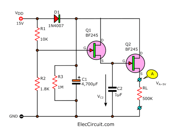
As long as there is this voltage still on. The capacitor C1 will be charged until the operating value is through D1. And there is a voltage of about 2.3V to the gate of Q1 as well because it passes through the voltage divider R1 and R2.
This ensures that Q1 will conduct current and C2 will be charged. The output voltage at the source pin of the 2nd MOSFET is the constant voltage at 5 volts. The two MOSFETs are connected in a voltage divider.
How it works
When the power is gone Capacitor C1 temporarily supplies power. The gate pin of T1 is now not powered, so C2 is not charged again. But it will discharge slowly because Q2 has a very high input resistance.
The voltage across C2 will remain almost constant. C2 will supply a working voltage to Q2, so it still conducts a voltage at the output of 5V.
The C1 discharges very slowly. Because the internal resistance of the MOSFET input is very high. And the load current is very low.
The output voltage at the source pin of Q2 will remain constant at 5V until the voltage drop across C1 falls below 5V.
But Q2 will continue to conduct current. The output voltage is lower than 5V.
To ensure the correct operation of the circuit. Choose C2 as MKT or Polyester Foil.
Shoping List
Q1,Q2: BF245, FET transistors
D1: 1N4007, 1000V 1A Diodes
0.25W Resistors, tolerance: 5%
- R1: 10K
- R2: 1.8K
- R3: 1M
- C1: 4700uF 25V Electrolytic capacitor
- C2: 1uF 50V MKT capacitor
You can see: Regulator 5V-6V-9V-12V at 1A using IC 78xx
And see more:
- Basic Dual DC Power Supply 6V
- Change the output voltage of IC-7805 diode
- Make cheap 6V battery charger from mobile charger
What is more?
You can look other power supply circuits: Click Here
Related Posts
I love electronic circuit. I will collect a lot circuit electronic for teach my son and are useful for everyone.
Everybody try it, it workz great!!!
Please i need a 2klm transmitter with a simplified circuit diagram that works effectively..
Please kindly provide me with a circuit diagram for a UPS for with 12VDC and 6VDC and a power of 100W
Which type of battery can be used? does NiMH work? I would like to use it for my DT Coursework
Can you please help me by sharing China UPS schematic circuit diagrams (Any Model)
Thanks and regards.
Mushtaq
Not try yet, but I think D7 is wrong side
Hello Khac Tan,
Thanks for your visit. Yes, you are correct. And I just update it and add new simple circuit for CMOS IC.
It is easy, too.
Thanks a lot
Apichet
Hi, I tried number of circuit configurations for mini UPS for wifi routers using buck converters and 3S BMS given by Youtubers. Though I used original Samsung Li-ion 18650 batteries, the circuits wont give more than few minutes of backup time. I am actually sick of wasting time and money.
I am interested in your circuits and would be grateful if you could share a circuit for mini UPS for 12v, with 18650 batteries using transistors and kind.
Thank you in advance and look forward to your response.
Hello Upul,
We have the Li-ion 18650 batteries in our storage.
But did not experiment with it yet, but this concept is quite interesting, maybe in the future, we will look into it.
Please stay tuned.
Thanks a lot
Yeah, i need this too..