
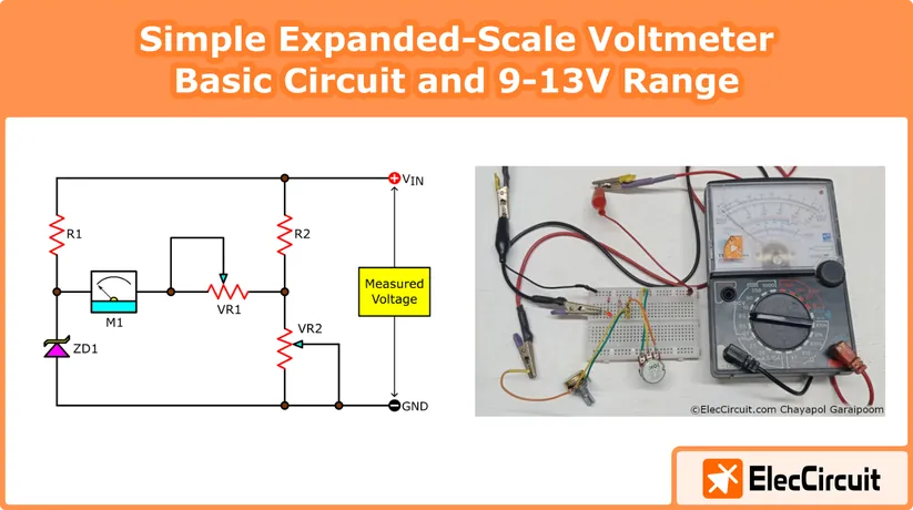
A normal analog voltmeter begins its measurement from zero. However, in this circuit, it does not start at zero. Instead, it shows the changes from a certain point. The result is a scale that is easier to read, more accurate, and more flexible.
It takes a constant reference voltage and then compares the measured voltage to it. We can apply this idea to many things. For example, it can measure 12V battery voltage (9V to 13V range) or be adapted into a thermometer measuring temperatures from 26 to 35 degrees Celsius.
All of these applications work using the same basic principle and with only five common components. Let’s learn about the design and concept further.
Why Would We Need This?
Suppose that we have a half-dozen or so 12V batteries, and we want to know how much charge is left in each of them. We don’t really care about the exact voltage level. We just want to know which one needs recharging.
A digital voltmeter will do the job. It even tells us the exact voltage level. However, since the digital voltmeter displays the voltage as a numerical value, it can be easy to overlook or misread at a glance.
On the other hand, an analog voltmeter displays a more obvious needle moving within the dial, which can be easier to notice if, say, one of them has a less-than-ideal charge level.
For instance, as shown in Figure 1, the discharged and deteriorated 12V lead-acid battery read 8V on the digital voltmeter (ready for recycling). On the other hand, a fully charged and functional one shows a reading of 12.6V.
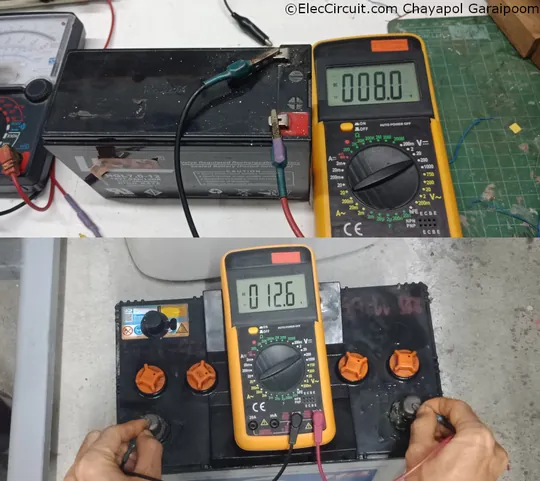
With a difference of about 4V, we would be able to tell at first glance on the analog voltmeter, based on the needle’s movement on the dial, which battery is working and which is not.
That said, the problem with an analog voltmeter in this case is its measurement ranges—or the lack thereof. When measuring a 12V battery, we would need at least a 15V range. Some may have a much higher range, like 50V or 100V.
As the measurement range increases, the visibility of the needle movement decreases. Instead of a quick dial swing when reading low or high charges, we would have to squint to see the difference.
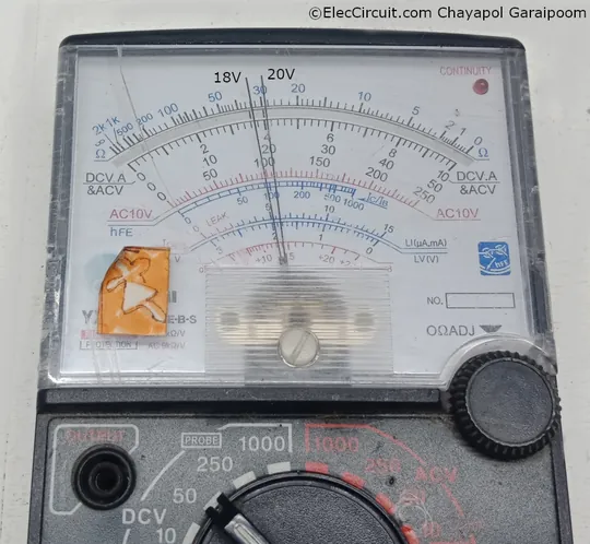
As shown in Figure 2, using a 50V measurement range, a 2V difference is almost unnoticeable on the dial.
Wouldn’t it be more convenient if we could set the minimum dial position (0%) to the minimum battery charge voltage and the maximum dial position (100%) to the fully charged voltage?
Today, we will do exactly that by compressing the typical 12V battery voltage range into a much more usable analog voltmeter scale.
Expanded-Scale Analog Voltmeter Circuit
Since the circuit is rather simple, let’s take a look at it first. As shown in Figure 3, it consists of a variable voltage divider, a Zener diode reference circuit, and an analog voltmeter between them.
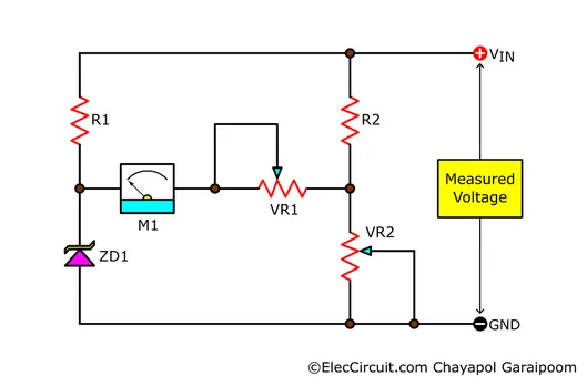
The ZD1 and R1 pair sets a constant reference voltage for the voltmeter. R2 and VR2 form a voltage divider, reducing the source voltage for the voltmeter.
M1 reads the voltage difference between the Zener reference voltage and the voltage divider output. Lastly, VR1 adjusts the measurement range by limiting the current flow through M1.
The measuring voltage is connected to the circuit as a normal power source. The circuit requires no additional power supply.
How It Works
The operation of this circuit is fairly simple. In particular, it relies mainly on the voltage divider principle, which we have talked about before.
In this section, we’re mainly analyzing this circuit using basic theory and ideas, which might not behave exactly the same in practice. To see that, we’ll have to wait until we test this circuit.
There are three key nodes we need to focus on, which are points A, B, and C, as labeled in Figure 4. The voltage at these nodes determines the voltmeter reading.
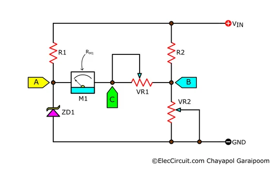
At point A, the voltage closely follows ZD1’s Zener voltage when the measured voltage (VIN) is greater than the Zener voltage. In this case, ZD1 is working in reverse bias and maintains a constant voltage across it.
However, if the measured voltage falls below the Zener voltage, ZD1 will stop conducting, and the voltage at point A will drop. R1 limits the current through ZD1 when it’s reverse-biased.
At point B, the voltage depends on the ratio of R2 and VR2, as well as the measured voltage (VIN). We can easily work this out using the voltage divider formula:
$$V_{\text{Point B}}=\frac{VR2}{R2+VR2}\times V_{IN}$$
When the measured voltage changes, point B’s voltage will also change accordingly, as long as the resistance ratio remains unchanged. Importantly, the relationship between the voltage at point B and VIN is linear.
For example, if R2 and VR2 shared the same resistance, the voltage at point B is always 1/2 the measured voltage. Where 1/2 is the ratio k.
$$k=\frac{VR2}{R2+VR2}=\frac{100}{100+100}=\frac{1}{2}$$
Then,
$$V_{\text{Point B}}=k\times V_{IN}$$
The voltage difference between points A and B drives the voltmeter circuit (M1 and VR1) as it spans between these two points.
However, because VR1 and the internal resistance of M1 (let’s call it RM1) form another voltage divider, the voltage directly seen by M1 is actually between points A and C (VAC).
We can calculate it using a similar formula:
$$V_{AC}=\frac{R_{M1}}{VR1+R_{M1}}\times V_{AB}$$
This particular formula differs from the previous one in that we use the voltage across points A and B (VAB) as the multiplier rather than the measured voltage (VIN).
Unlike the R2-VR2 divider, the M1-VR1 pair is not directly referenced to the supply rails. Instead, it operates across the voltage difference between points A and B.
Expanded-Scale Analog Voltmeter Circuit for 12V Batteries
Now, with the circuit analysis out of the way, let’s look into the practical circuit for checking the charge level of 12V batteries. But first, we need to define the range for the measured voltage, as it will affect our choice of components.
Defining the Voltage Range
The measurement range depends on the following values:
- VMIN. This is the lowest measured voltage value. At this voltage, the voltmeter’s needle appears at the minimum, or 0V, on the dial.
- VMAX. This is the highest measured voltage value. At this voltage, the needle jumps to the maximum position, or full-scale, on the dial.
Both of these voltages correspond to the voltage we expected to see from our 12V batteries. Under normal operation, these batteries typically range from about 10.2V to 12.6V, while a heavily discharged unit may fall to about 9V or less.
Based on this information, we decide on a 9V to 13V range (VMIN = 9V and VMAX = 13V). The table below gives a clearer picture by comparing the measured voltage to the needle position on the dial.
| Measured Voltage (VIN) | Needle position on the dial | |
| VMAX | 13V | 100% |
| 12V | 75% | |
| 11V | 50% | |
| 10V | 25% | |
| VMIN | 9V | 0% |
At this stage, the analog voltmeter’s original voltage range is irrelevant, as we can adjust the effective measurement range later using VR1.
Practical Circuit
The resulting circuit is shown in Figure 5. The needle position on the analog voltmeter dial changes corresponding to the measured voltage (VIN)—0% at 9V and 100% at 13V.
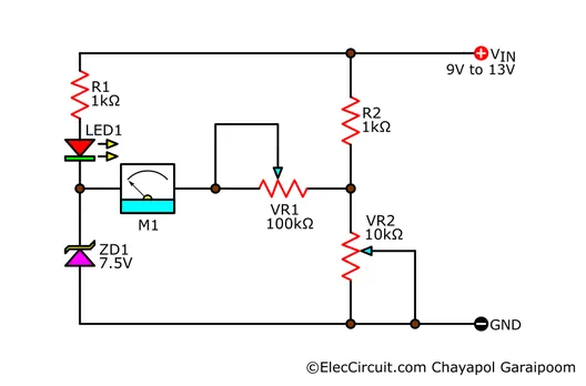
We’ve also added a small LED (LED1) after R1. It acts as a visual indicator, turning on when the measured voltage rises above approximately 9V and turning off when it falls below that level.
Since the circuit is quite simple, we just assembled it onto a breadboard, as shown in Figure 6. In the following configuration and testing, we’ll use a variable power supply as the measured voltage because it’s more convenient.
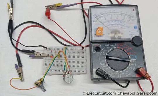
Configuring the circuit and setting the measurement range consists of a few simple steps. First, we turn VR1 to the maximum position (highest resistance) and then apply VMIN to the circuit, 9V in this case.
Next, use VR2 to adjust the voltmeter’s needle position to 0% (0V). In this case, we adjust VR2 to roughly the midway point, or about 5kΩ as calculated earlier.
The analog voltmeter itself is in a 2.5V full-scale range, as shown in Figure 6. This means that, at a measured voltage of 13V, the voltage across the voltmeter (VAC) must be 2.5V.
Then, we increase the measured voltage (VIN) to VMAX, or 13V. Afterward, we decrease VR1 resistance until the voltmeter reading is full scale (100%), or 2.5V = VAC.
Be careful not to let the voltage across the voltmeter overshoot the 2.5V scale. If the voltmeter reaches full scale too quickly while increasing VIN, try using a larger VR1 value or adding another resistor in series.
Conclusion
This non-zero expanded-scale voltmeter circuit works quite well. For applications concerning voltages with small variations between them, such as measuring the charge level of 12V batteries, this circuit makes these differences much easier to distinguish on an analog voltmeter.
However, the idea of using voltage dividers and non-zero reference voltages to determine the measurement range can also be applied to many other applications.
For instance, the measured voltage can be tied to the NTC thermistor, allowing us to observe room-temperature variations within a smaller range, such as 25°C to 30°C. The same idea can also be applied to a photoresistor for monitoring ambient light levels.
In the future, we might explore more of these ideas or applications that make use of this expanded-scale voltmeter circuit.
Want to learn more?
We’ve extended this article on Patreon (16 pages, 2513 words) with extra content, including practical testing, design notes, and meter measurement range adaptation.
👉 Read the extended version on Patreon
Exclusive posts on Patreon come free of advertisements and in PDF format with high-definition illustrations. Membership fees will allow us to continue to do what we do without as much reliance on advertisement. Thank you very much.
Hello. I’m Chayapol, but I could also go by Aot. I write and draw illustrations for ElecCircuit.com.
I usually cover articles related to digital electronics, logic, or basic principles or ideas on the site.