These are the 5V/3A power supply circuit for those who want to have a microcontroller or power digital supply source. For use in experiments such as logic circuits and/or microprocessor types or even Raspberry Pi. These require 5 volts at a high current rate of up to 3A rate.
The first circuit is very simple, with the LM323K, LM123, or LM223 being the only ones. But they can supply a 5V fixed output voltage and can be connected to load current up to 3 amps.
Note: If you cannot buy the above IC or want an easier circuit, let’s try the LM350 or 7805 with a transistor.
Please read below; there are 3 circuits that are interesting.
Using LM323K
It is easiest.
How it works
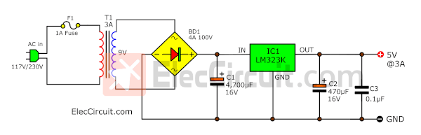
As shown in the circuit below. It uses only LM323K.
Here is a step-by-step process.
In the circuit, there are only a few components. Such as the transformer acts to reduce the voltage from the AC main (230V or 117V in your country) to AC 9V.
Then, the bridge diode(BD1) converts the AC voltage into a DC voltage. A C1 capacitor will smoothly filter the pulsating voltage into a steady direct current. After that, the IC1-LM323K regulator will maintain a constant voltage of 5 volts at the output.
In this IC, there is also a good protection system, such as short circuit or overcurrent usage and overheating protection, etc.
The C2 is a noise frequency filter. The C3 is the output filter.
The components list
IC1: LM323K or LM323T (To-220) THREE-TERMINAL 3A-5V POSITIVE VOLTAGE REGULATORS
C1: 4,700µF 16V Electrolytic capacitor
C2: 0.1µF 63V Polyester Capacitor
C3: 470µF 16V Electrolytic capacitor
T1: Transformer primary 9V at 3A.
BD1: Bridge diode 4A 200V.
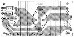
Building
All components in this circuit except the transformer can be assembled on the PCB layout above. In installing the IC1, we need to be careful and never short-circuit its inputs or outputs to the heat sink.

Using LM350 as 5V 3A regulator
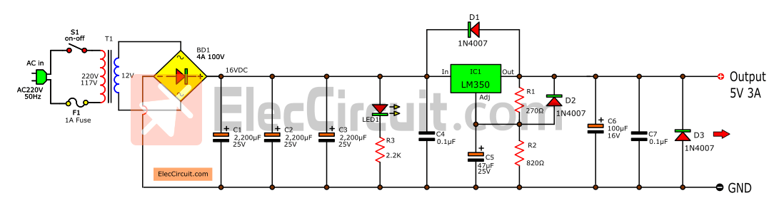
Many people say that they can’t find LM323. I think we can use the LM350 instead, but we only need to modify a few additional devices. See the circuit diagram below.
How it works
This circuit uses more components. The workings of the unregulated power supply are similar to those of the circuit above.
But we added 3 filter capacitors in parallel, resulting in a combined capacitance of 6,600µF. It comes from my original experience, choosing capacitances of 2,200µF per 1A output current.
We should do this because it is cheaper than buying 10,000 µF, and it’s easy to find too.
See the LM350 regulator. Normally, we can adjust the output voltage from 1.25V to 30V by setting the voltage by R1 and R2.
When we want 5V output, we should use R1 = 270Ω and R2 = 820Ω. Why do I know it? Because I read…
Recommended: How to use LM350 Regulator
Diode protection
As a datasheet, we should add both diodes to protect the backward voltage from the output and others. It can kill the LM350.
Transient noise filter
Both C4 and C7 (0.01µF to 0.1µF) filter out the transient noise that can be induced into the supply by stray magnetic fields. C5 and C6 maintain a stable voltage.
Other parts
LED1 is powered on display like other circuits.
The components list
IC1: LM350 Three-Terminal 3A Positive voltage regulator
Electrolytic capacitor
C1-C3: 2,200µF 25V
C5: 47µF 25V Electrolytic
C6: 100µF 16V Electrolytic
C4,C7: 0.1µF 50V Polyester Capacitor
0.5W Resistor tolerance: 5%
R1: 270Ω
R2: 820Ω
Others
T1: Transformer, Primary 12V at 4A.
BD1: Bridge diode 4A 200V.
Prototype testing
We assembled the electronic components of the 5V/3A power supply circuit onto the perforated PC board. And it is important to install the heatsink for the LM350 because it gets quite hot when in use. We tried connecting the load. It can supply approximately 2.7 A of current. If you need more current, the transformer size should be increased to 4A.
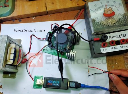
Note: In the prototype, we installed a 12V 0.1A fan to reduce the heat of the IC and other devices. While it works at currents higher than 2A.
If you need a PCB design, please let us know in the comment box.
Using 7805 and PNP transistor
If you cannot buy both the LM323 and LM350, You can use normal IC-7805 and power transistors to make a 5V/4A power supply circuit.
It may be the cheapest circuit.
How it works
We intend to design this circuit to be smaller for saving.
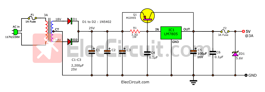
The circuit is similar to the circuit above. Here is a step-by-step process.
In the unregulated power supply, we use it as a full-wave diode rectifier. In a circuit like this, we need to use a center-tap transformer, 12V-CT-12V.
As usual, we know that 7805 is a 5V/1A regulator IC. It runs great. But it’s too low a current for us. We need a helper who is kind.
So, the PNP power transistor, MJ2955 or TIP2955, will boost the current to 4A max. When the current flows through R1, at B-E of Q1, it gets a bias current. It conducts current more than IC.
Read: 7805 datasheet & Pinout
Overvoltage protection
But this circuit has a disadvantage: it is without overvoltage protection and short-circuit protection This problem can be easily and effectively solved with a fuse and a Zener diode.
Fuse Easy, but sure
Normally, we do not connect a short circuit or use overcurrent. Using just one fuse is economical. It definitely works better than complex electronic circuits.
Zener over-voltage protection
We have learned that when the voltage reaches the VZ of the Zener diode, it will have a lot of current flowing through it. If we use a 5.6V Zener diode and the voltage exceeds 5.6V.
Learn: How the Zener diode works
This is the safe voltage level of the digital circuit. There will be a lot of current, causing the fuse to burn immediately.
Is it easy?
The components list
IC1: LM7805, 3 Terminal 1A Positive voltage regulator
Q1: MJ2955 or TIP2955, 15A 80V PNP transistor
ZD1: 5.6V 1W Zener Diode
Electrolytic capacitor
C1-C3: 2,200µF 25V
C5: 100µF 16V Electrolytic
C4,C6: 0.1µF 50V Polyester Capacitor
R1: 3.3Ω, 1W Resistor tolerance 5%
Others
T1: Transformer, Primary 12V at 4A.
BD1: Bridge diode 4A 200V.
F2: 3A Fuse
F1: 1A Fuse
Conclusion
These circuits are linear power supplies that have many advantages. such as very low noise and no leakage current. It is important and easy to create. Use a small amount of components. When broken, it is easy to repair, and is very durable, etc.
But they have a disadvantage: low efficiency. It has high energy losses, such as in this circuit. If we want it to supply a current of up to 3A, we must use a transformer of at least 4A, a filter capacitor of more than 6,000µF, and a large enough bridge diode. Roughly more than 4A. Which is definitely the size of these large devices. Therefore, this circuit is large as well.
However, if you consider the advantages and disadvantages, there is value in creating it. We think it’s an excellent power supply.
Read also:
- Many ideas of 12V , 5V Dual Power Supply Circuit at 3A
- 5V 3A Switching Regulator circuit using LM2576
- 5V 5A Power supply circuit
Keep reading: 5V 3A power supply for digital circuit
Related Posts


I love electronics. I have been learning about them through creating simple electronic circuits or small projects. And now I am also having my children do the same. Nevertheless, I hope you found the experiences we shared on this site useful and fulfilling.
Hi.. it’s a nice article.. 🙂
about your PCB layout above.. whether it’s okay when the LM323K is not attached with heatsink?
and second, I don’t know how to soldering the TO-3 package+heatsink.. I never use this kind of component before.. could you tell me more about it..
Thanks..
Any integrated like the lm323 but with this OUTPUT 5V 10A 50W ??
is this circuit can work on an USB charger circuit?
Hi,
Yes, It can be used for USB charger.
is there any replacement of ic LM323k or LM323t in Microprocessor power supply circuit, 5V 3A by LM323K project…??? plz do reply soon