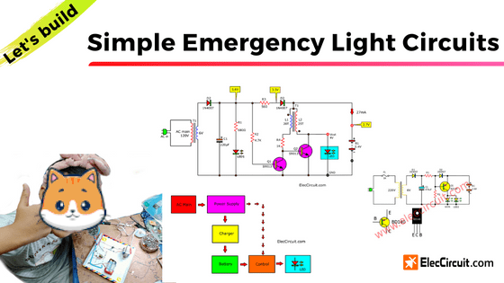
This is a simple emergency light circuit. Why should you build this?
Imagine that there was a sudden power outage. Everything was dark. You can’t see anything, so you have to fumble around looking for a flashlight. It’s inconvenient, isn’t it? Or worse, an accident could have occurred.
I was just like you before. But now we create these circuits. It makes our lives better during a blackout. When the power fails, the LED in this circuit will instantly glow for almost an hour until the battery is depleted. At least we might be able to see the corridor, or we may be able to investigate the cause of the power outage. It may be caused by a short circuit or some other reason.
There are a total of five circuits in this post. The first two have already been tested, but the other three have not been tested yet.
Simple emergency light circuit by Ai
My daughter (Ai) built this circuit by herself; we have been continuously using it for over 8 months, and it still works well. when there is heavy rain and the power goes out. This circuit starts running, and the LED will light up immediately. The battery is also still fine.
The more special thing than other circuits is in normal conditions (no power outages). The LED will slightly glow. It has enough light for dark corners in the house such as stairs, hallways, etc. It also consumes very little electricity in this state.
But like any other circuit we have built in the past, we modify an old component to be used in the circuit, so it’s very economical. It is also a very simple circuit; since my daughter could make one, you definitely can.
How it works
Idea of the circuit in Block Diagram
First, let’s look at the block diagram of this project so it can be a broad guideline for our circuit design.
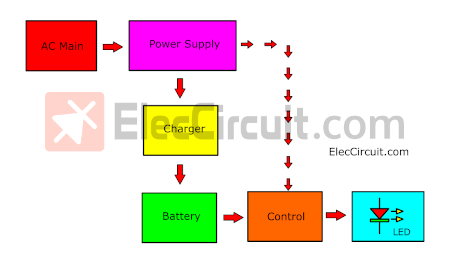
Most emergency light circuits have these main features.
The operating principle of this circuit can be divided into two cases:
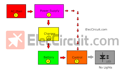
Normal state
In normal circumstances, the sequence of operations is as follows: The AC main flows through a Power supply to charge the Battery. But a part of the Power supply flows to Control a LED to turn off.
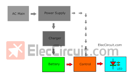
Power outage state
No AC Main, Power supply, and Charger. The Control discharges the current from the Battery to itself to light up the LED.
The concept of this circuit design
When creating various electronic projects, it is important to choose components according to our specified conditions, such as performance, size, and price.
Like other projects, we focus on sufficient performance, small size, and low cost. Emphasizing the concept of recycling e-waste to be used again is even better.
Select the primary component first
The LED
The LED must shine brightly in the dark, just like a general LED flashlight. Luckily, we have a lot of broken cheap LED flashlights.
Examples of LED flashlights:

Internal parts of one of the LED Flashlights:
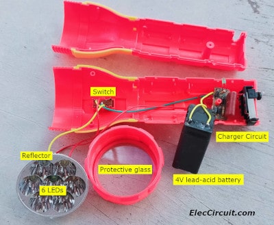
It normally uses a 4V lead-acid battery. when the battery runs out. It can be recharged many times. But when used for a while, the battery will start to deteriorate. Shortening the usage time after fully charged to the point that it became unusable. Since they are quite cheap, some may just discard them and buy a new one instead.
Even if the battery is already broken. We can still modify the LED part to use it again as a lamp, and it is quite an excellent lamp.
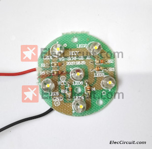
This is the PCB for the LED part of the flashlight; now let’s check the circuit thereof. The circuit schematic is shown in the picture below.
It consists of 6 LEDs, so it’s fairly bright.
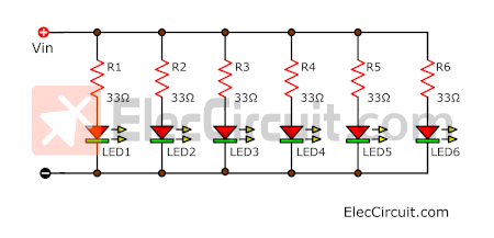
The circuit is very simple; it consists of 6 LEDs (LED1 to LED6) in parallel, and each LED has resistors (R1 to R6) connected to it. It reduces the current accordingly.
Because Vin is supplied by a 4V battery, but each LED only requires a voltage of about 3.3V, This way, all the LEDs are uniformly lit, and the total current is only about 60mA to 80mA.
The Battery
Coincidentally, I have two Ni-HM AA batteries. They are very old, but they still work. They can supply a voltage of about 2.4V at a current of about 2,000mA combined.
Normally, this level of voltage is capable of powering white LEDs. But they are still not fully illuminated.
Step-up DC-to-DC converter circuit
And for that, we would need a step-up DC-to-DC converter circuit to convert the voltage from 2.4V to 4V. The easiest way is to use a simple unregulated flyback circuit , or Joule thief circuit.
Read more about how we use it in an Automatic Solar Light Circuit.
https://www.eleccircuit.com/simplest-automatic-solar-led-light-circuit/
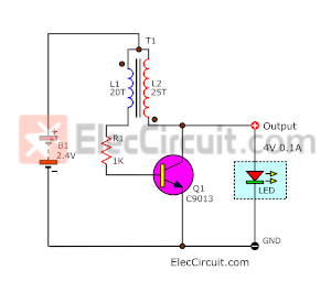
It only uses a few electronic components, consisting of a transistor, an inductor, and a resistor. This circuit is therefore only suitable for the low-current constant-current type of load.
For T2 of T1 in above
My daughter uses a ferrite core measuring 10 mm in diameter, 5 mm thick, and 7 mm in width.
Then, wrap 30AWG solid wire onto the ferrite core; L1 is wrapped 20 turns, and L2 is wrapped 25 turns.

There is one notable point. The little dot in its symbol marks the beginning of each wire. In the circuit, L1 is connected to the end of L2 and then combined with the positive of the battery. If we were to connect it in the wrong polarity. It won’t oscillate or produce a higher voltage.
The Charger
The next step is about the battery charger circuit.
When there is no power outage. The battery needs a current to keep it fully charged at all times, making it always ready for outages.
According to the principle that the battery should be charged at 0.1C rate when charging the 2000mAh battery. From said principle, it should use a 200mA charging current for 10-12 hours to get it fully charged.
But in this circuit, we don’t need that level of current. because normally the chance of a power outage is very small. Therefore, we have a lot of time to keep charging the battery until the power outage occurs. Making it better to charge the battery with a lower current, like for example below 0.01C rate.
With this low charging current, the battery will not get hot at all. And when the battery is fully charged, the voltage drop across it is definitely no more than 1.55V per battery. So it has a longer service life.
#Simplest two Ni-HM battery charger circuit
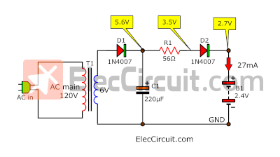
This circuit is the easiest, but it is enough for these batteries. T1, D1, and C1 are acting as half-wave rectifiers in the DC power supply.
The voltage drop across C1 is 5.6 volts, which is enough so that the battery can be charged. The charging current is defined by R1. It’s about 27mA, enough to slowly charge the battery fully.
We put a D2 in it to prevent the current backflow from the battery. It is like a one-way water valve to complete the battery charging system.
The Control circuit
Next, let’s look at the circuit used to control the LED to light up immediately when the power goes out. Normally, we always use the simplest method first. If the step-up DC converter circuit above is stopped, the LED will turn off.
And looking at the circuit below, if we were to stop the current (IR1) from flowing to the base of the transistor by pulling IR1 to the ground with a virtual switch.
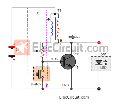
The virtual switch will turn on when it detects the current from B1. Causing the transistor to be off and the LED to stop immediately.
The component that will act as this simple virtual switch is the transistor. Now we add it to the circuit and modify the circuit a bit.
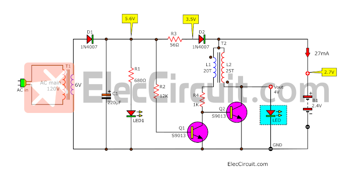
When a small current from the power supply flows through R2 to the Base of the transistor (Q2), it will conduct a higher current from D1, T1, and R1 to the ground by passing through C to E.
Cutting off a bias current for B of Q1, causing it to not conduct. But there is a weak current from the battery (B1) flowing through a secondary coil of T1 to LED1. But this is a low voltage (2.4V) enough so it cannot power LED fully.
But on the other hand, when there is no voltage from the power supply or one comparable to the power outage. The Q2 turns off.
So, the current from B1 can flow through R1 to Q1, and the simple Joule thief circuit starts to kick in, generating a high voltage of up to 4V.
Causes LEDs to light up at their highest brightness.
We put D1 in to protect the bias current to Q2 when there is a power outage.
Next, we take each part and assemble them together into a complete circuit.
In fact, thinking of a new circuit is just putting these small circuits together like this. It allows us to think of larger circuits.
Building emergency light circuit
This project was built entirely by my daughter herself. She opted to install the entire circuit on cardboard because it was easy and very economical.
Although this project looks like a toy or an educational tool for children. But after more than 7 months, it still works fine.
As the saying goes, “Black cat or white cat, it doesn’t matter as long as it catches mice.”

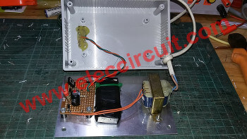
An example of the positioning and layout of various components:
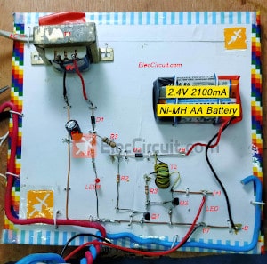
The electronic components should be installed tightly, especially the transformer and the batteries.
Pay extra attention to the AC main input terminal on the transformer; it must be covered with electrical tape to prevent a high-voltage shock.
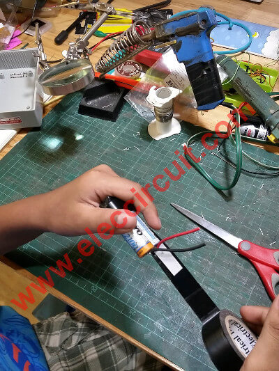
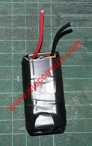
As for the batteries, my daughter installs them. By soldering directly without a battery holder the same way my son used to do before.
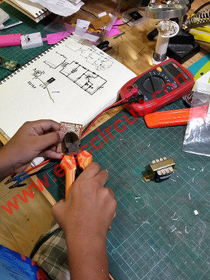
Testing Circuit
When we finish assembling the circuit and checking for installation errors, the next step is to do the first test of the circuit.
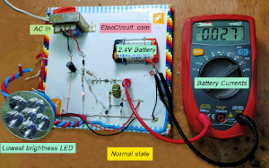
When we plug the AC main into the circuit, LED1 will glow, and the flashlight LED will also glow very dimly. Next, we need to measure the charging current for the battery. It should be about 27 mA.
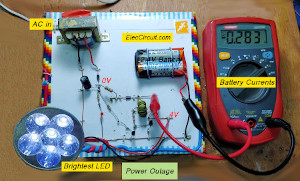
Then we try unplugging it. First, LED1 has to turn off because there is no voltage from the power supply. And we will notice that the current coming from the battery will increase to 283mA, indicating that this circuit is working normally.
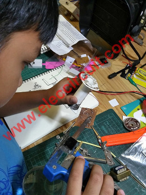
My daughter is testing Simple Emergency Light Circuit that she made herself.
Components List (in the completed circuit above)
Q1, Q2: C9013, 0.8A 50V, NPN transistor
D1, D2: 1N4007, 1000V 1A Diodes
C1: 220µF 25V Electrolytic Capacitors
0.5W Resistors, tolerance: 5%
R1: 680Ω
R2: 12K
R3: 56Ω
R4: 1K
B1: 2x 1.2V 2100mAh Ni-MH AA batteries
T1: 6V 0.3A Secondary transformer
T2: See in text
Flashlight LED, others
From now on, my daughter will not be afraid of storms anymore, even if the power goes out, she doesn’t have to be afraid of the dark. Because she has emergency light circuits that she proudly made herself.
If you think this circuit is too complicated for you, then check out an easier circuit. which my son (Ai’s brother) built many years ago. It’s a great inspiration for Ai to create this current version of the emergency light.
The first and simplest emergency light circuit
This is the first mini emergency light circuit that my son has built. It is quite small, and it uses an LED as a light source when there is a power outage.
Let’s get started.
How it works
The schematic below is for a compact emergency light circuit that uses a few components consisting of a transistor instead of a relay. And it also uses two rechargeable AA nickel-metal hydride batteries to store enough energy to drive a small LED lamp.
It works like any other general emergency light. It is used to provide lighting automatically in the event of a power outage.
- In normal conditions, the charger section will charge the battery up.
- When there is a power outage, the controller will drive the LEDs.
This mini emergency light is special in that it does not use a relay to turn the LED on and off. But it uses the transistor to act as the switch instead.
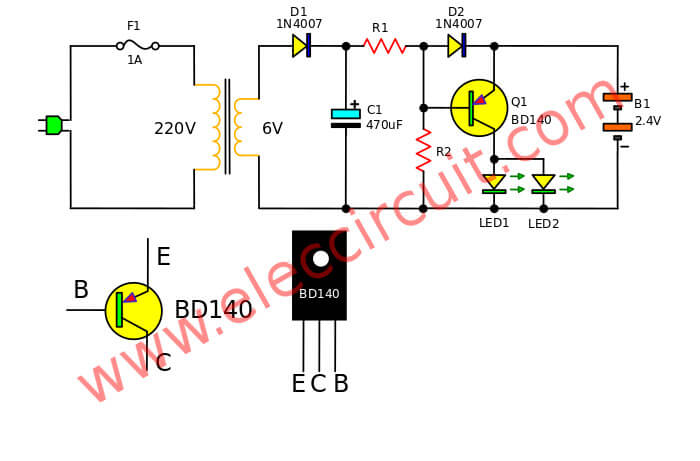
It begins with AC power being fed into the circuit. There is fuse F1 to protect the circuit from the overflow current.
The transformer T1 will reduce the AC voltage from 220V to about 6V. This low AC voltage will then be rectified by diode D1 in a half-rectifier configuration. Then the resultant DC voltage will flow through a resistor R1 and diode D2 to the battery, charging it with 55mA current.
At this point, the LEDs are not lit up just yet. Because the base of transistor Q1 receives a higher voltage than the emitter, this is called a “reverse bias.” So, the transistor will not conduct current, and the LED does not light up.
But during a power outage, the voltage at the base of the transistor is reduced to a level below that at the emitter, and some current will flow through resistor R2 to the base of the transistor. causing the transistor to get a forward bias.
Making the transistor conducts current from the battery to the LEDs, lighting it up.
The current from the battery will not send any feedback voltage to the transformer. Because there is diode D2 blocking the way by placing itself in the reverse bias between the battery and transformer.
Components list
Q1: BD140, PNP transistor
C1: 470uF 16V, Electrolytic capacitors
R1: 22 ohms 1W
R2: 560 ohms
D1,D2: 1N4007 Diode
T1: 6V 0.5A transformer
and other
How to build
He makes this circuit on a universal PCB or perforated PC board. Because it is an easy circuit.

Easy to put parts on perforated PC board
Solder pins or legs of the components
Cut the leg of components with a cutter plier
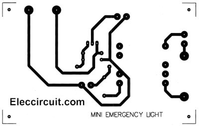
But if you build it on PCB you can use the Single-sided Copper PCB layout.
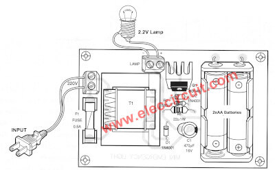
Here is the components layout.
Note: He does not use a conventional lamp because he does not have one; instead, he uses a super bright red LED.
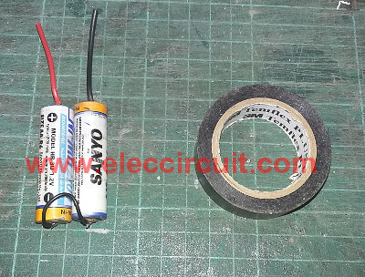
Because we do not have a 2 AA battery holder. We so soldering wires directly.
And, use electrical tape to protect a short circuit.
The Completed 2.4V AA battery.
Drilling for mounting LEDs, they use only 3 LEDs, because of the low power consumption.

Install all parts to the versatile box. Then use a hot glue stick. the LED legs with the box.
Look inside this project.
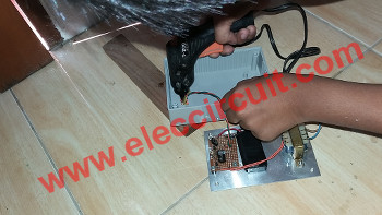
How to use an application
He installs this corridor. He tested the device without connecting to power. If the battery power is normal and the normal LED. The LEDs will be lit up immediately.
But when the plug and LEDs are not illuminated. The charge current can be checked from the voltage across the resistor R1 is calculated by Ohm’s law.
I (current) = E (voltage) / R (resistance)
Assuming the voltage drop across the resistor R1 (22 ohms) at 1 volt charging current values are equal:
= 1 volt / 22 ohms
= 0.045 Amperes
or equals 45mA
This circuit uses a charging current of 50-60mA.
When building this project completed Try it together as a video below.
Recommended: How does an SCR thyristor work?
Note: We apologize if the article below uses the wrong language. We will rewrite them later.
Simple emergency light circuit with charger
This is a Simple emergency light circuit with a charger that light on 30 minutes after the power outage, so use normal transistor as base of circuit.
At the time of power failure. Especially during the night. Many people do not like the dark. Emergency lighting systems on the market, it has expensive. We make a emergency lights with a simple electronic circuit. But it is enough to use it to some degree. This circuit makes light bulbs for nearly 30 minutes after the power outage.
As Figure 1 First of circuit that use to drive the lamp, which consists of a transistor that work as switches, by has Q1 is driver. The transistor -Q2 acts as the signal amplifiers for provides to lamps- LP1-LP3 glow up.
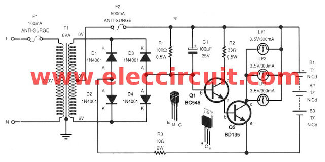
Figure 1 the 30-minutes-emergency-lighting
The second is the ac line voltage detector and the battery charger. By transistor-Q1 will open circuit when voltage from AC line power still. (at its base will has voltage not exceeds 0.7V) and when not have voltage from power supply Q1 will close switch down, cause the lamps glow.
The low voltage power supply can be build the low voltage transformers of center trap type. And rectifier diode D1-D4 to the secondary of transformer. which has 0V another position.
If voltage of AC line power still, the first positive half cycle side, current will flow through the transformer to fuse and through battery. which is A nickel-metal hydride battery to charge the battery by current is limited with R3 current will flow back to point 0V through diode D1 or D2
Another half cycle later. current will flow like the first half cycle. but will flow to transformer by through Diode D3 or D4. The driver transistor will still hold switch off.
When not have ac line power (power outage) current will flow from the positive polarity of battery through resistors-R1 to bias to base of Q1, cause Q1 conduct current, Q2 so also conduct current. The lamp so glow up as during time equals voltage of battery still which about nearly 30 minutes
How to builds
This project use a normal components so can assemble on the universal PCB board. With the wiring and various components can view of the example in Figure 2. We should check carefully the polarity of the electrolytic capacitors, diodes, transistor correctly.
The components list
0.5W Resistors
R1-100 ohms
R2-33 ohms
R3-10 ohms, 2W Resistor
C1-100uF 25V Electrolyte capacitors
D1-D4-1N4001, 50V 1A Diode
Q1-BC546
Q2-BD135
LP1-LP3-Lamp, 3.5V 300 mA
Without transformer Emergency light circuit
This mini LED emergency light circuit without transformer is used to automatically give lighting when ac line power goes out. Which they consist of one lamp, a battery, and a low voltage sensor. This project’s design takes advantage of simple circuit techniques and cheap.
Special feature:
1. Small-sized: output with 2.4V 5W lamp or 3V LED and a 3V battery.
2. No transformer is so Lightweight and easy to build.
3. No relay so be Silent and small.
4. etc.
How it works
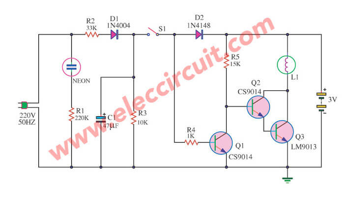
To begin with, we use a 4-5V dc power supply without a transformer. Next, the AC 220V input to passed trough R1 to cut current down and D1 to rectifier AC to DC in half-wave type. Then, the dc pulse or fluctuating signal is smoothed with C1-capacitor. Which has voltage dropped across of 4.5Vdc
And then SW1 is used to turn on-off the next circuit as a sensor, control, battery charger, and lamp circuit. First of all, in normally power the lamp go out not light since current pass to R4 to the base of Q1 cause it is bias so high current flow through D2-diode, R5-resistor to collector-emitter of Q1. Thus not has a current bias to the base of Q2, Q3 ( Darlington transistor) cause they do not conduct current, so not has current pass Lamp, it so not light.
And later the power AC line goes out, So not has current through S1, and then current from 3V battery not current through D2 be due to diode not allow current as is a one-way street. It will not work if you put it in backward. And making Q1 does not work.
But this battery current will flow to R5 through base Q2, Q3 they so bias current is a result of high current flow to Lamp glow light up at once.
Friends can use Nicad Battery or NiMH battery the size is 1.2V x 2 gives the light has just enough. This circuit can charge automatically battery.
Recommended:
- Try simple FET Preamplifier circuit (Very high impedance)
- Uses of capacitors | Capacitance | RC circuit time constant and Coupling
- Simple transistor intercom circuit
Components List
Q1,Q2,Q3: C9014,C9013, 0.8A 50V, NPN transistor
D1: 1N4148 75V 150mA Diodes
D2: 1N4004 400V 1A Diodes
L1: 2.4V 5W Lamp
L2: Neon Lamp
S1: Slider Switch
C1: 47µF 50V Electrolytic Capacitors
0.5W Resistors, tolerance: 5%
R1: 220K
R2: 33K, 1W resistors
R3: 10K
R4: 1K
R5: 15K
B1: 3V battery (AA 1.2V)
Note: However, this circuit is not suitable for practical applications. Because of the small size
12V emergency light circuit using transistor
If you ever feel annoyed when power failure while working or business. and in an important area. Such as the way up the ladder and in the bathroom could be dangerous, or shops at night you might be case it gets stolen the products. Emergency lighting is necessary to replace the main light during a power failure.
An internal emergency light circuit will have battery backup. As usual, This circuit will charge to store in batteries. But when the electricity fails, it does the opposite is the battery will discharge into a lamp to provide light immediately.
The working of a circuit
Simple battery charger circuit with voltage charging.
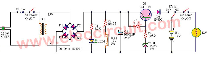
The complete emergency lighting circuit is shown as a circuit diagram below. Which core of the circuit is a simple charging system.
– Start the electricity AC220V 50Hz of the house is entered through F1 (Fuse 1 Amp) to prevent damage. If the circuit malfunction.
– Later, pass through the switch S1 is turned on-off circuit.
– And the transformer T1 converts the voltage from AC220V to AC15V that voltage is also AC.
– When passed to the set of 4 diodes bridge D1-D4 into the direct current voltage (DC).
– But the electric current is not smooth, Therefore the capacitor C1 is a smoothing filter power up.
– LED1 be used to display the power-on of the circuit which R1 is a current limiting that suitable for LED1.
– The DC electric current to the transistor Q1 is connected as a regular circuit. To control both the voltage and current properly. For charging the battery.
– The diodes D5 prevents the flowing back of the battery’s current into the circuit again.
– The voltage regulated is controlled to a constant, by value diode, Zener ZD1 15.6V, with the output voltage will be 15V (low voltage of the Zener diode 0.6V).
– While battery voltage is zero volts or no power, R3 is used to set the maximum current of the circuit is about 500mA.
– the circuit will charge the current battery steadily When the voltage of the battery, the charging current is reduced.
– Until the battery voltage is 13.8V or to full charge. The charger will not stop charging circuit as other
But current is flowing through the battery charge is low at about 100mA. To compensate for the loss of the battery to full power always.
– Normal relay contacts to the battery charging circuit. As any power failure, it will switch to battery connected to a load or a light bulb instead. And before to cutting the S2 switch on the lights to activate or not. When the electric current failure up.
building the circuit
You can make PCB as Figure 2 is a simple layout. Then you put all parts in PCB as components layout on Figure 3 which easy to really build. Please check error for wiring and various components or see carefully for is the polarity of the electrolytic capacitors and Diodes, transistor, lamp, transformer, and more.
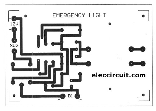
Figure 2 The PCB layout.
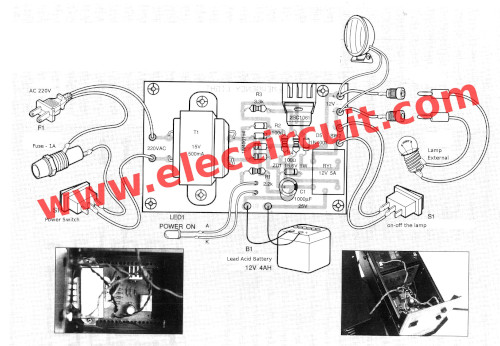
Figure 3 the components layout
You may be packing all the equipment into the same box. With key ingredient is the B1 battery voltage 12V. In the prototype, the current size there is 4 AH, is the battery of sealed lead acid. It does not have any maintenance throughout the lifespan. It is more expensive than conventional batteries.
The transistor Q1 – 2SD313 is TO220 case, Vce=50V, Ic = 3A, power=25W. 2SD235 2SC1061 2SC789.
The tests and using
After operates the circuit is complete into the box. Now that you the test used.
– This circuit is plugged into a powerhouse. Then turn on the power switch S1 can hear the relay(RY1) click , start to connect the battery to the charging circuit and LED1 lights display power on.
– When switch off S1 to relay to the battery to the load and LED1 will off. Show that section cutting is loaded with circuit running. I will try to test the circuit. By the Connect the battery and the load circuit terminals to the output.
Then plug in the power cord about 1 hour, (if the battery is not charging). Try turning the power switch S1 current flows from the battery to the load. If the load is a lamp, it lights up. But 12V a lamp may not light up, do not panic. Because the battery is not charged until full. Must be plugged in for about 10-12 hours.
After that, try to cut off power switch S1 again. The lamp will be fully lit. If the test results show that both battery and charging circuit is functioning properly. You can find the right position to get it.
Here are a few related circuits you may find helpful, too:
- Transistor series voltage regulator with overload and short circuit protection
- Universal nicd and nimh battery charger using LM317T
- What is switching power supply vs linear, how does it work?
Download This
All full-size images and PDFs of this post are in this Ebook below. Please support me. 🙂


Related Posts


I love electronics. I have been learning about them through creating simple electronic circuits or small projects. And now I am also having my children do the same. Nevertheless, I hope you found the experiences we shared on this site useful and fulfilling.
Very nice,how to get attach with you to get like this circuits.
Very simple & easy method.
Thanks for your feedback.