Let’s build a small solar AA battery charger. In an era of expensive energy better. In an era that energy is more expensive every day.
Alternative energy is a good solution, to solve immediate problems, or renewable energy to do the work well.
Solar energy is an alternative that we can use another kind. For this project, we use it to charge a small battery, we must first understand the working principle of the circuit before.
How it works
Battery charger with solar cells consists of three parts are…
1. The solar cell panels are used to change sunlight energy to electrical energy into direct current. Normally we would put solar panels are connected to each other. Until the voltage level as needed.
Which, has the principle same battery, is sunlight cell series to increase the current. And this current production, depending on the geographic location, temperature and the amount of sunlight each day is important.
2. The charger controls the voltage in this project. We use the dc booster circuit to rises voltage from solar cell panels up to charge a battery.
3. The battery is backup electrical energy of solar cells it needs time.
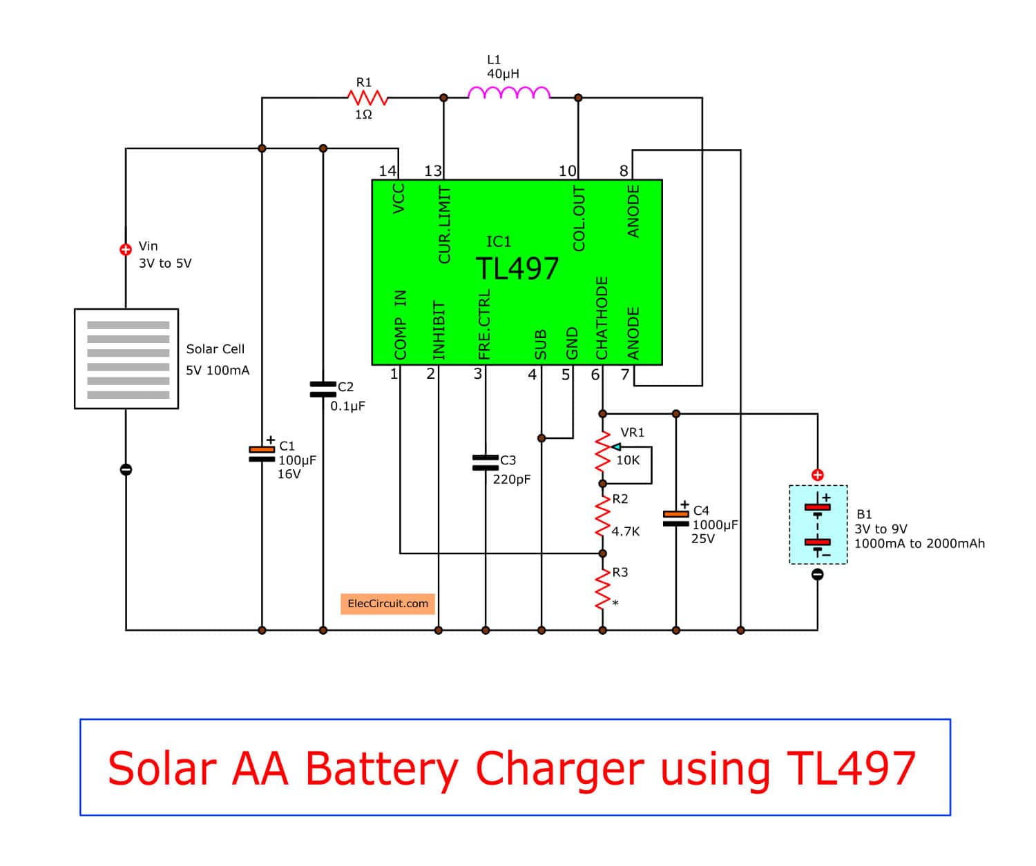
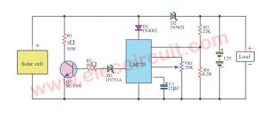
Photos complete circuit as Figure 1, the heart of the increase voltage circuit is IC1 in TL497 is a DC to DC converter circuit types.
There is resistor R1 between VCC and pin 13 that limit current working of circuit. And the capacitor C3 is determined value of switch frequency in working of 50KHz.
We can adjust the output voltage as needed by potentiometer VR1. The output voltage that change be controlled by compared circuit inside IC1
Characteristics of working overall is This circuit will increase the size of the input voltage of 5 volt solar panels. (Normal the voltage 3-5volt, current 100mA) To output the voltage maximum 12-15 volt at current 30-70 mA.
To provide sufficient the voltage to flow into the battery charging. The specifications of the IC can be up to 15 volt input voltage and maximum output current 470-500mA.
Building and circuit assemblies.
We prepare PCB size is shown in Figure 2 above. Then solder a resistor and IC on the PCB. Equipment is high, the coil L1 and capacitor according down.

For coils L1, we use the finished coils easily. When soldering all the equipment already in place. Should check the accuracy again. When everything is complete, then process testing circuits.
Equipment list
0.5W Resistors, tolerance: 5%
R1: 1 ohms
R1: 4.7K
R1: 1.2K
VR1: 10k potentiometer
C1: 100uF 16 volt Electrolytic
C2: 0.1uF 50V Ceramic
C3: 220pF 50V Ceramic
C4: 1000uF 25V Electrolytic
IC1: TL497, with socket
What’s more? You can look other power supply circuits: Click Here
Testing and deployed
We bring solar cell panels place in sunlight location, then measure an output voltage with the DC volt meter. Which we can adjust output voltage by charging the resistance of VR1. When less sunlight, will have output DC voltage about 15 Volt (the maximum resistance of VR1) In the case of the midday sun, for example during the day, We measure an output voltage, while load is not connected. will have maximum voltage 18-20 volt.
Using to charge the battery,
– The output voltage should not be too much. We adjust VR1 until the voltage of battery with less than full power for about 1 volt. Because solar panel in this project is small. So suitable for charging the voltage to the nickel cadmium battery NiCd. or Nickel Metal Hydride AA or AAA size NiHM only.
For example, in the case of a fully charged battery, nickel metal hydride. Which has the voltage at 1.2 volt pack of 4 pcs., So we adjust VR1 until the the voltage is 6 volt.
– The charging time, Battery charging time depends on the capacity of the battery. (MA h). If there is a large capacity, it will take longer. We can be calculated from : The capacity of the battery divided by the charging current as the battery 500 mAh. When it is charged with 50mA current, it takes about 10Hour etc. However, the current from the solar cell will be uneven, depending on the intensity of the light. May take longer for about 12 hours.
If everything is normal. We plan to install on the box or the angle the sun. As a prototype. With each other’s ideas.

Related Posts

I love electronics. I have been learning about them through creating simple electronic circuits or small projects. And now I am also having my children do the same. Nevertheless, I hope you found the experiences we shared on this site useful and fulfilling.
The above comment is Spam! Please remove.
It’s awesome in support of me to have a site, which is useful designed for
my know-how. thanks admin
Hi……
It is very good to see, we are save energy, but when battery is fully charged then we have to made a breckdown ckt to protect the cell’s,
And when the Charging voltage is below the min voltage (e.g. 6V) then its start the charging again…
is there any alternative for tl497
yas, i want to know for any alternative for TL497 too . i can’t find it >>> please , is there any alternative for TL497 ??
i want to know,if i can use other component than TL497?
Hi,Rohit,Mostafa,Baraka
Please check here:
https://www.digikey.com/product-search/en?x=0&y=0&lang=en&site=us&KeyWords=TL497
https://t.co/T5lYkNC7op
Hi, this charger seems to be the perfect fit for what I am trying to do.
I have one question, L1 choke.. 40uF but what amp?
If I were to make this myself what would the specs be? I can only find a 2 amp and 20amp online at this time..
Any input will help
Thanks
I haved try with this circuit a lot of time , and in each case I had only the same input voltage !
I replaced all equipments with new ones, and the same result !
Could you help me about the solution ? 🙁
Thanks 🙂
if we r going to use MOSFETs , PIC microcontroller mppt , transformer and input solar source then we can found more voltage ????
if we have to make this project then ???
can u make that??
Could this circuit be configured to charge NiMH batteries?
Bill
Am very intrested in such projects because i really love technolodge and i also make projects but i really want to know make an aircraft