Although the LM386 audio amplifier is very old. But they still have a lot of usefulness. Thanks to the inventor of this IC. If you want to increase the sound volume of your audio player. The LM386 is a good choice, because of the low voltage consumption and functions well with a battery.
LM386 Datasheet
You just finished your own audio circuit, but the sound is too low.
Many people use LM386 to increase the sound volume to drive a speaker. Should you use it as well?
But…it would be better if you read the LM386 Datasheet first.
LM386 is a low voltage audio amplifier. It shapes like IC-741 in the DIP-8 form factor. Thus, it is small and easy to use. Even if the size is small but it does sound great.
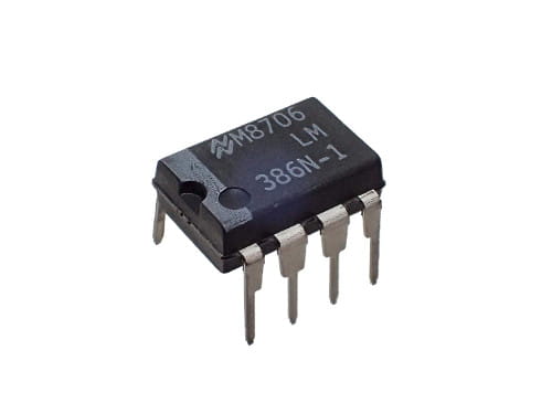
Cr: LM386 of National Semiconductor. I like ICs from this company.
LM386 Pinout
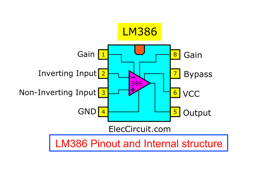
We often use LM386 in the DIP-8 packet, there are 8 pins used for connections as same as other packets. For example, SOP-8, TSSOP-8, etc.
LM386 features and specifications
- Give enough power — Common Power of the output is about 700mW at VS = 9V, RL = 8Ω, THD = 10%. Imagine you listen to soft music at prefer corner.
- Consume a wide supply voltage range of 3.7V to 15V.
- Consume a low supply current — in case of no input signal is 4mA to 8mA.
- Internal voltage gain is set to 20 or 26dB (without other parts).
- The voltage gain can be increased to 200 or 46dB, by connecting a 10uF capacitor across pin 1(+) and pin 8(-).
- The gain between 20 and 200 can easily be controlled by connecting a resistor in series with the capacitor.
- Typical Low harmonic distortion: 0.2%
- The frequency response is from 40Hz to 100 kHz rate.
- Frequency bandwidth: 300kHz in common
By having a lot of benefits, many small electronic appliances use it as the speaker driver. Examples for, radio, MP3 player, Mini Portable speaker, Etc.
More the circuits, the more we understand
My thought is slow. I can not understand a large amount of information in a short length of time. Has this happened to you?
I have used images, they help me understand things more.
Also, I like the circuit diagram and circuits. I have learned and got so many ideas out of it.
Let’s learn more about LM386 circuits.
x20 Amplifier
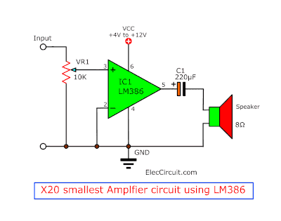
The smallest amplifier gives a gain of 20 with the fewest parts.
It is indeed an amplifier circuit. Even with one IC and one capacitor.
But Its output current is quite low (low driving power). Thus, in real usage, we might need a louder sound. We can increase it in a simple way as below.
X200 great small amplifier
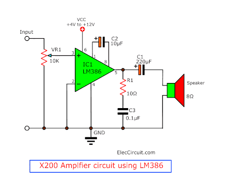
The gain of this circuit rises up to 200. Because we connect the C2 capacitor to the IC by the positive leg of C2 at Pin 1 and another at Pin 8.
But sometimes a too high gain is not good for us. We can control it with a resistor.
X50 lower gain of LM386 amplifier
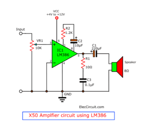
We add the R2 resistor in series with C2 to reduce the gain to 50.
LM386 Amplifier with bass boost
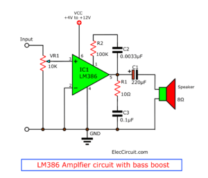
Sometimes you may want more bass than normal. It also can be done easily. By adding R2 resistor and C2 capacitor in series as the circuit above.
This circuit has a bass booster. The output gain depends on a bass frequency. For example, Gain 25dB: 100Hz, and Gain 19dB: 2kHz.
Almost forgot, that some components on the circuit above have their use.
- We can adjust the volume by VR1.
- Both R1 and C3 will keep the sound good. They also improve the stability of a high-frequency load.
Do you know that LM386 can be used in other types of circuits?
LM386 Square wave oscillator
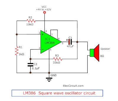
The LM386 can also be used to create a square wave oscillator circuit. It makes creating an audible alarm with the speaker easier. Because this IC is a type of op-amp. Thus it is a good choice when making an oscillator circuit as well.
According to the circuit above, the output frequency is approximately 1KHz, it can be changed by C2. More the capacitances less the frequency and vice versa.
What is more? Let’s build LM386 projects.
Mini LM386 audio amplifier
If saving energy is important for you, this circuit is a good choice. Because you can use it with a 9V battery at 5mA current. But it has an output gain of about 50 and power of 300mW to 500mW if used for 8 ohms speaker.
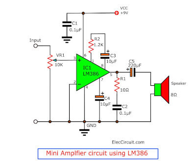
LM386 mini audio amplifier circuit
For example, you made an AM receiver circuit with the LM386 as the amplifier for a 0.5W, 2 inches speaker. Powered by a 9V battery that can provide enough energy for a long music session.
Flexible in choosing parts
You can use similar components, that can replace one another.
For example:
- The loudspeaker — can be 4Ω or 8Ω @ 0.25W or 0.5W in any size as the space required.
- Voltage supply — ranging from 4V to 12V. But lower the voltage, lower the watts as well. It is reasonable.
- The voltage of capacitors — The higher voltage can be used instead of the lower voltage. Like C5 is an electrolytic capacitor, 50V can be used instead of 16V. But… Of course, it is more expensive.
About LM386’s Pin 7
Pin 7 (bypass) is used to protect the input of the LM386 amplifier circuit from the noise created by the power supply. Usually, we connect it to the ground with a 10uF capacitor.
But if the power supply is mostly clean and stable (i.e. Battery, Linear regulator) then the capacitor is not needed.
How to builds
If you want to build these circuits. It can be built on the universal PCB or even the breadboard. But if you prefer the PCB board instead, you can make it as a PCB layout and components layout below.
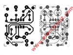
The PCB and components layout of the LM386 audio amplifier
Parts list
0.25W Resistors, tolerance: 5%
R1: 10Ω
R2: 1.2K
VR1: 10K Potentiometer
Capacitors
C1, C2: 0.1μF 50V Ceramic
C3,C4: 10μF 25V Electrolytic
C5: 220μF 16V Electrolytic
Semiconductors and others
IC1: LM386, Low voltage audio amplifier
SP1: 8Ω 0.25W speaker
B1: Battery, 9V Or 9V power supply circuit
Look at more:
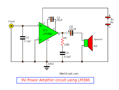
9V Power Amplifier using LM386
Other than the circuit above, this is also a 9V amplifier circuit but with a higher gain of up to 200.
LM386 mini amplifier
How it works
To begin with, the signal goes to the input pin 3, non-inverting input. This is a signal amplifier in the non-return phase form.
They have…
- The C1 absorbs the noise to protect the input.
- The C2 increases the gain of the amplifier. More gain can be achieved by increasing the C2 capacitance. But, a higher value will result in greater distortion (Should be lower than 100μF).
- The output comes out of pin 5 of IC1.
- Then, the signal passes through the C4 coupling capacitor, this makes the quality of audio signals better. And block all DC voltage going to the speaker.
- Both R1 and C3 are connected in series. They keep the high-frequency response better.
Recommended: Classic active tone control circuit using ICs
Parts list
0.25W Resistors, tolerance: 5%
R1: 10Ω
R2: 1.2K
VR1: 10K Potentiometer
Capacitors
C1: 0.01μF 50V Ceramic
C2: 10μF 25V Electrolytic
C3: 0.1μF 50V Ceramic
C5: 220μF 16V Electrolytic
Semiconductors and others
IC1: LM386, Low voltage audio amplifier
SP1: 8Ω 0.25W speaker
B1: Battery, 9V
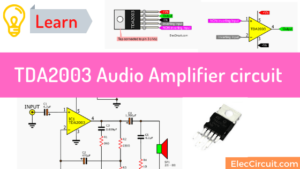
Read Next: TDA2030 stereo amplifier circuit
500 mW Power Amplifier using LM386N
This is another interesting circuit. because it has the power of 500mW if used for an 8Ω speaker at distortion is Less than 1%.
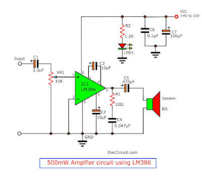
This circuit is similar to the circuit above, let’s take a look at the different points that have been changed.
- The LED1 lights up to show if the circuit is on.
- And, capacitors C6 and C7 act as filters to smooth up the supply voltage.
- The sound signal flows through VR1, which controls the volume up or down.
Hand-picked related articles you may want to read:
- Simple transistor intercom circuit
- Simple electronic projects
- 1.5V LED flasher circuit using BC556 and BC546
What is more?
Parts lists
0.25W Resistors, tolerance: 5%
R1: 10Ω
R2: 1.2K
VR1: 10K Potentiometer
Capacitors
C1: 3.3μF 25V Electrolytic
C2, C6: 0.1μF 50V Ceramic
C3: 10μF 25V Electrolytic
C4: 0.047μF 50V Ceramic
C5: 470μF 16V Electrolytic
C7: 100μF 25V Electrolytic
Semiconductors and others
IC1: LM386N4, Low voltage audio amplifier
LED1: Red LED 5mm.
SP1: 8Ω 1W speaker
B1: Battery, 4V to 12V
Download This Post as a PDF and all PCB layouts
Conclusion
We love LM386 audio amplifier, me too. Because it uses a battery. We can test and make them more. It is easy and cheap. What do you think about it?
Sure, this may not enough for you to read more LM386
Keep Reading: LM386 Stereo Amplifier with Bridge model
Related Posts

I love electronics. I have been learning about them through creating simple electronic circuits or small projects. And now I am also having my children do the same. Nevertheless, I hope you found the experiences we shared on this site useful and fulfilling.
Hi, I want to know how to give input, and can I use 3.5mm jack to input and use it with mp3 player
How to give input plz tell fast????
Hi,Shital
Thanks for your feedback.
You can use input for any low audio, example: CD audio, MP3, others.
Hi! nice site i would like to ask ..Where i can find the block diagram or schematic diagram for making amp for tweeter and low driver
High > need amp driver
Mid > already have sound standard ex1200
Low > need amp driver
sir,pls tell me how to give input …???
What is the size of this pcb?
hello my name is mike , i am working on the project using the 555 ,but can anyone tell me which pin is whih and wheres does everything connect to because i have no idea where to connect each component to its belonging pin, if anyone can help please comment as soon as possible, thank you
Hai can we connect two stage ic lm386 amplifier please send me circuit diagram of it to connect these stage with filter circuit and you site give very simple circuits thangs send me answer in my mail
Hi shubhendu,
Thanks for your visits.
Please ser printer the pcb layout on 300dpi per inch.
That was great.
Tanks
great …..!!!!!!!!!!!!!!!!!
useful …… give a info for the audio amplifier using blootooth connector without audio jack
email me small audio amp circuit
i ve a 8 ohm 4 watt speaker what value of capacitance would i ve to use as zobel capacitor? when i searched through the net i found it to be inducatance/resistance^2 So actually how do i khow the henry of the speaker
how to generate 85 dB sound?