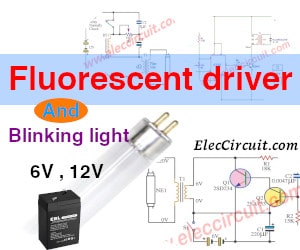
Fluorescent is a kind of light bulbs that get high popular to use in a house. But sometimes you need to use it with a battery, 6V or 12V. It cannot light up.
Here are 3 circuits of Fluorescent Driver. You may get ideas to fix your projects or learning.
Let’s get started.
Note: I have not tested these circuits. So, I cannot confirm it worked. Please decide Before you start building it.
4W Fluorescent driver using 555
This is a 4W 12V fluorescent lamp driver circuit. Using a 555 timer as main parts. When it uses a 12V battery has a consumption current of about 300 mA.
You may use it with a 12V AC Adapter or 12V battery.
The advantage of this circuit has a lot of brightness using less energy.
How it works
In the circuit below.
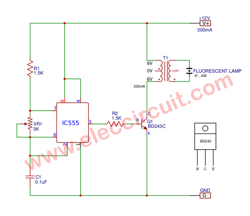
Figure 1: Schematic diagram of the 4W Fluorescent lamp driver
The 555 is working in astable multivibrator mode. Which the output current will be increased by transistor Q1.
Then, it will drive a transformer with a high current at the collector of Q1. It should be mounted with enough heat sink.
The transformer will convert low voltage AC to a high voltage to drive a fluorescent light up.
Read also: DIY Flashing Bicycle LED Taillight Circuit
Setting
First of all, apply the power supply to the circuit. We need to adjust VR1-5K. Use a multimeter at ammeter range. To measure the current flowing through in the circuit.
Then, partially adjust VR1 to read current about 300 mA. Which it is the fluorescent lamp lights in maximum.
Be careful
You need to be careful with high voltage at the transformer. If you touch it, you may be fatal. So, It should be installed in a sealed box.
Parts you will need
R1, R2: 1.5K Resistors 0.5W
VR1: 5K Potentiometer
C1: 100nF (0.1uF) 50V Ceramic
IC1: NE555P Timer
Q1: BD243C Transistor
T1: Transformer 6-0-6 / 220V
4watts fluorescent 6 inch
Recommended: DIY inductor coil from compact Fluorescent Light
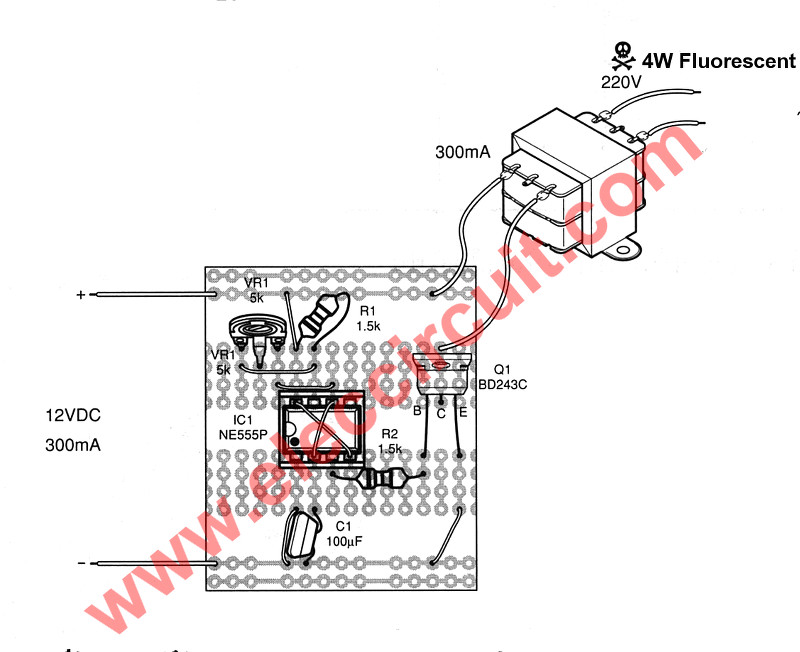
Figure 2 the components layouts on solderable PC breadboard
Read Also: AC dimmer for LED Bulbs using IC-555 & TRIAC
6V Fluorescent driver circuit
This is a small circuit, a few components, and light. You can get it is portable to gets a fluorescent light.
Which they use a power supply with four 1.5V AA battery (6V) only.
How it works
See the circuit below.
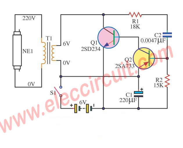
When you press a switch-S1. Then, the capacitor-C1 charge fully via R1 and R2. While C1 will charge fully. It makes the voltage to bias Q2.
Next, Q2 is biased and the Q1 is also running by biasing of Q1.
After that, the high current from a battery can flow to a primary coil (6V-0V) of transformer-T1 through work of Q1.
While the Q1 works. The voltage drops across C2 is low down. Next, Q2 will be stopped. The C2 will gradually discharge through R1 and R2. Completely, Q2 will begin running again.
Working like this makes the voltage at the primary coil of T1 AC voltage. And it induced current to the secondary coil is a high voltage approximately 220V. It makes the fluorescent glow up.
See: Many Simple 6V Power Supply circuits
Equivalent transistors
I search for other transistors that you can get it.
Q1: 2SD234 NPN transistor 60V, 3A, 25W, 3MHz. The equivalents are: BD241A, BD535, BD935, 2SC3179.
Q2: 2SA733 PNP transistor 60V, 0,1A, 0,25W, 180MHz. The equivalents are: BC212, BC257, BC307, BC557, BC212L 2N4061 KT3107K
T1: 300mA 6V transformer
12V Fluorescent blinking light
Here is a blinking light for a 12V battery. It can power a small fluorescent light bulb. See in the circuit below.
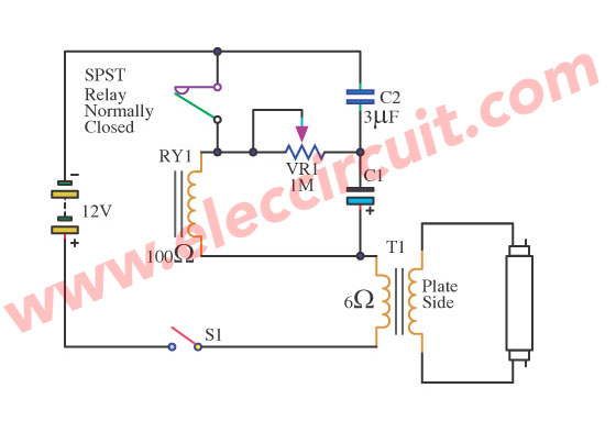
It uses the relay. To converts DC voltage of battery into AC voltage. This form is a mechanical technique without any semiconductor, transistor, IC, diode.
The relay will turn on and off the 12V Car battery. Each time of relay is opened circuit. The induction happens at a coil of the relay.
Also it induction from a low voltage at primary to high voltage at secondary of the transformer.
Which this high voltage can make a 24 inches fluorescent lamp glows. And it is flashing as the emergency is when your automobile has a problem.
Even this circuit is simple and old. But sometimes you may need to use it.
You may also like these circuits too.

Related Posts


I love electronics. I have been learning about them through creating simple electronic circuits or small projects. And now I am also having my children do the same. Nevertheless, I hope you found the experiences we shared on this site useful and fulfilling.
Hi,
Please tell me the substitution of these transistors.
I have 2 questions Sir..
1) Fluorescent light by 6V power circuit can drive a cfl of 5watt or ten watt or not??
2) is there any other same category transistor other than these transistors??
Thnx In Advance!
Nice 2010 infograph : )
Thanks for the schema, it’s very useful.
any other substitute for the transistors thanks
Hi, vicks
Thanks for your feedback.
can thiswrk also 2SC5002 transistor
Hi,vicks
Please look at “NOTE” in this article.
I’m not sure for 2SC5002.
can it light 11watt cfl
Hi,vicks
Thanks for your feedback.
Yes,it is lower light.
hello sir ,i replicated the circuit bt i could not light a 11watt cfl but if i gut it,it will light pls what do i do?
hello sir ,i replicated the circuit but it does not light ungutted cfl ,why sir ?
Hey vicks
can you want to know about some advance circuit technology,lets watch my fb page……i have some easy assamble,and ultra low cost circuit.
Hey vicks
This circuit is just 4-5 watt,….so you unable to use any of 11w component,….if u like this circuit,then use same 2 circuit for one cfl.
Hello, can u know about auto cut switch,…..i want to use for my 500w inverter as a autometic inverter.
Awesome, Thanks.
with out a transformar can’t a fluorescent lamp work?
Sir,i want that it curite gives 11wat cfl flashing.plz its can possible.plz reply.
Can transformers be used differently depending on input voltage?
Hello Windows95,
Thanks for your visit.
Yes, you can different transformer voltage. But IC555 use voltage lowest at 5V only.
You may try 6 transformers.
I feel interested in you to try this circuit. Please do not forget to share with me.
Thanks