Overload transformer protection circuit
This is a Simple Overload transformer protection circuit. When the load uses too many currents until the transformer almost damaged. Suddenly a relay will cut off the load. The transformer is safe.
How circuit works
To begin with, the DC voltage power from the secondary coil of the transformer will be charged to C1 through D1.
Second, turn on the S1 to the circuit. The current can flow to the load with the contact NC of RY1, and both R1, VR1 in parallel.
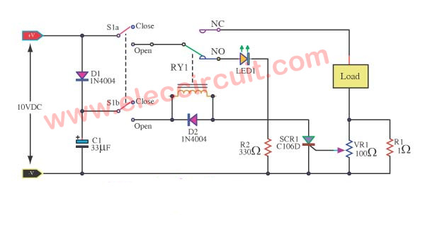
Figure 1 The overload protection for transformer
The VR1 controls the current of the load, and to set the limited current of SCR1.
When the overload occurs, SCR1 is triggered to work or conduct. The relay is running and contacts of the relay are in NO position.
So the LED1 light. The R2 reduces the current of LED1.
The load is disconnected from the transformer. So now we have a current flow through the coil of the relay, SCR1, R1, and LED1 only.
After the relay runs. If we want to turn the protection circuit to work again. Just switches S1 to the off position and unplug it.
Then, reconnect the protection circuit is ready to work again. Do not forget, VR1 to adjust the load current is equal to the current transformers only.
For the D1, you may use LED instead. All parts to the power supply circuit used for a maximum of 10 volts (no load). No filters to smooth current. Using 1A transformer only.
Recommended: How does a SCR thyristor work?
How to build this project
You can build easily this circuit due to having a few components. We recommended that put them on universal PCB board. The SW1 control circuit on-off.
The parts you will need
Semiconductors
Q1—C106D 400V 4A SCR, Quantity: 1.
D1,D2—1N4004 400V 1A Diodes, Quantity: 2.
LED1—5mm LED, Quantity: 1.
Resistors (All 0.25 watt, 5% metal/carbon film)
R1—1 ohm 5W, Quantity: 1.
R2—330 ohms, Quantity: 1.
VR1—100 ohms Potentiometer, Quantity: 1.
Capacitor
C1—33uF 16V Electrolytic, Quantity: 1.
RY1—Relay with SPDT 10A min. switch
Coil Voltage 12V. Coil resistance 150-600 Ohms, Quantity: 1.
S1—DPDT toggle switch
Perforated board
FET Overload Current Protection
This is the Overload current Protection circuit for a normal power supply. It uses a FET to drives a load. If you worry that the power supply will damage. When the load uses too much current, or a output is a short circuit. This may help you.
How it works
As the circuit diagram below. Usually the load work. A small current flows through S1 and R1 to gate Q1-MOSFET. It is switched ON. A much larger current flows through Q1, D1, R3, and Load.
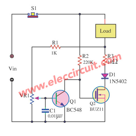
Then, if the output overload. The higher voltage occurs across R3. Then a small current flows through R1 and VR1 to a base of Q1, It allows a much larger current to flow between the emitter and collector.
So, the voltage across between gate of Q2 and ground is zero. Then, it is switched OFF no current to load, it is safe mode.
You will reset circuit by pressing the normally closed pushbutton switch-S1.
The D1 act as absorbs the current spike to protects MOSFET and drive current to load circuits.
C1-capacitor smooths any noises to base Q1.
You can adjust a VR1-trimmer potentiometer to set the sensitivity of the circuit.
Note:
Q1—can use many number, BC548 or 2SC1815 or 2N3904. But it has different legs.
Parts you will need
Q1_BC548-45V 0.1A NPN Transistor__Quantity: 1
Q2_BUZ11-MOSFET, Quantity:1
D1__1N5402-3A 100V Diode, Quantity:1
C1__0.01uF 63V__Ceramic Capacitor, Quantity:1
VR1__100K__Trimmer Potentiometer, Quantity:1
1/4W Resistors tolerance: 5%
R1_1K, Quantity:1
R2_220K, Quantity:1
R3_10 ohms, Quantity:1
S1_Normally Closed Pushbutton Switch, Quantity:1
Overload protection circuit for regulator IC
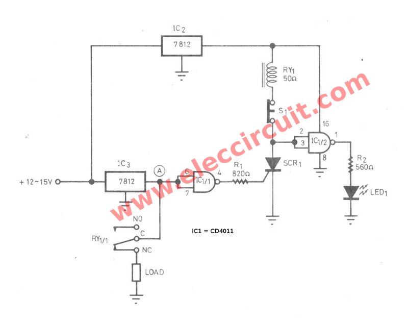
This is an overload protection circuit for voltage regulator IC. Often We use a 7812 regulator, 12V power supply. If its load is a short-circuited, or use too much current. It will be too hot and may damage. This circuit can help us, save time, don’t change a new one again.
How it works
Overload protection circuit for voltage regulator IC
In the circuit, IC3-7812 as the 12 volts regulator will supply voltage to load,through the contact C-NC of the relay RY1. In normal,the point A will has state is “1”, cause the output of IC1/1 is “0”, so no current to trigger gate of SCR1. Thus the RY1 not works. The IC1/2 and LED1 are used to display working of the relay.
For load short-circuit time. At point A will has state is “0”, cause the output is “1” , so has current to trigger gate of SCR1. Thus RY1 will works, cause its contact C-NC is separated out as cutting the load.
While the LED1 will light up to you will see that, does load have the current flow too much? The IC2-7815 is used to supply current for this protection circuit that works freely not depend on the output voltage of IC3.
After that check and modify completely the load, and need to connect load again, press the reset switch-S1. Which is the normally closed push button switches in this experiments,when load short circuit for 1 second. The Relay-RY1 will cut the output away. A resistor-R1: 820 ohms
If we not use these level parts, this may will cause the current gate is lower than the SCR1 can work completely. The logic level “0” at input of IC1/1 about 0-4 volts and logic level “1” about 7-12 volts.
Related Posts


I love electronic circuit. I will collect a lot circuit electronic for teach my son and are useful for everyone.
plzz send project on thermal overload protection for transformer using ATmega8 microcontroller
When you are going for posting the circuit and its description, please check…. the circuit what you have given and the description is not related and its not the overload protection for transformer. Sorry to say this… please check it… thank you.
Plzz send me the project of overload protection of transformer
Can u please share me the details of ur project
sir plc send me full view of over load protection for transformer data
“overload protection for transformer” component name&details sent me please, i want immaditily because of i am submit my mini project in monday please consedar me.and replay please.
Hello deepika.p
I am happy. You like this circuit. But I never make it. So I not sure it works. However, If you have time you should try to build it. I believe you can make it well.
it works
The Leaning towards the project ideas
Hello Nasri Haji,
Thanks for your visit. Yes, these circuit is great for learning. I am sorry if it is clear explaining. My English is poor. But I am improving.
We are friends please wait for me. I will update it. And if you have any ideas you do not forget to share me.
Thanks again.
Apichet
class h audio amplifier circuit diagram
Hi,
I very much appreciate your request. The class h audio amplifier circuit might be a great idea. Now we do not have it. I and my dad will compile how-to and ideas to create simple electronic projects for hobbyists and beginners.
Please be patient. 🙂