How to test a diode. You should build a diode test circuit. Why? If you are a beginner. You need to do it. Normally you can use a multimeter to test it easily. But it cannot test all types of a diode. For example Schottky Diode. It runs on a high frequency. Sometimes, it cannot test with a normal meter.
But this circuit can check it. Because it runs on a high frequency with an oscillator inside. Also, sometimes you need to test it faster. This circuit can check the diode the good or bad. And can indicate its polarity.
They use 741 op-amp and a few parts so easy. Two LED display indicates a tested diode.
How to test a diode
First of all, if you do not know how to test a diode with a digital multimeter. You can watch this video.
Cr: Justin Miller. It is nice.
Anyways, you need to build this circuit. It may be good for your work.
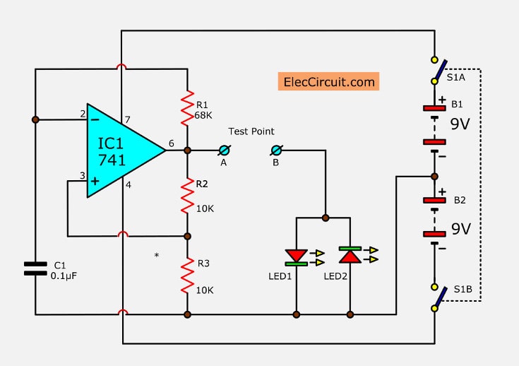
In the circuit.
There are IC1, R1, R2, R3, and C1 include as the oscillator circuit that generates the square wave out to pin 6. This signal will be an AC that is a symmetrical waveform.
So, if we connect the test point or both A and B terminals together. It causes both LED1 and LED2 will alternatively flash ON and OFF.
Then, if we take the diode to the A-B terminal.
By a cathode to A and anode to B. Now, the LED1 is in forwarding bias.
So LED1 will glow but LED2 will go out. Because it is a reverse bias.
If put the diode in backward, that anode to A and cathode to B. So LED2 will glow up. but LED1 will go out.
This indicates that this diode is normal.
But…
In case of the diode lack, LED1-LED2 will go out.
Then, if the diode shortens circuit, both LEDs will light up.
The transistor tester
Also, this circuit can be used to check the transistors, because the structure of transistors has a state like two diodes connected together, base-collector is one diode and base-emitter is other one diode.
When testing the same the general diode, but when testing between the collector-emitter lead. If normal transistor, the LED1-LED2 will must go out. But LEDs light up to show that short circuit between the collector-emitter, we cannot use this transistor.
How to assemble circuits
This simple project circuit can be assembled in the universal board, contain into a small box. Trying to install LED1, and LED2 to be close to the most testing. And LEDs of different colors to make observation easier. The 9-volts battery should be used in normal type because this circuit uses low current and so saving your money.
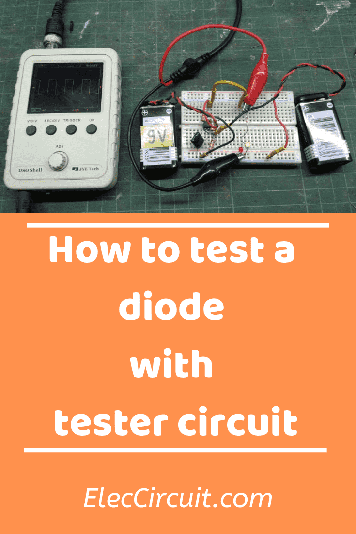
Try the circuit
For example, I try the circuit on a breadboard. It works. I can check all type diodes with a frequency. Which is better than a normal multimeter. It is suitable for repair the TV and all.
Note: Both LEDs do not need a limiting current resistor. Because it runs with AC pulse watch with Scope. So, the average current is lower.
The parts you will need.
IC1: LM741 op-amp IC
C1: 0.1uF 50V, Ceramic capacitors
R1: 68K, 1/4W Resistors tolerance: 5%
R2: 10K, 1/4W Resistors tolerance: 5%
LED1,2: Read in a text.
PCB,SW1,and more etc.
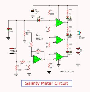
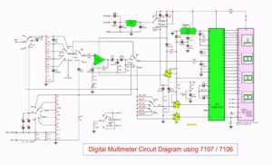
Related Posts


I love electronics. I have been learning about them through creating simple electronic circuits or small projects. And now I am also having my children do the same. Nevertheless, I hope you found the experiences we shared on this site useful and fulfilling.
Thanks a lot.
Hi, Salim Khan,
Thanks for your feedback.
Hey I just wanted to know why the op-amp 741 is required in this case? The circuit would work even if you would remove the op-amp and resistors.
Kindly illustrate the necessity of the op-amp 🙂
it is nice project using ic 741. –
must to be serial resistor of led s