Let’s build an ICL7107 digital voltmeter circuit. It is an important basis for other measurement tools circuits. Thirty years ago, we created this circuit very difficult. Now building a digital voltmeter circuit does not need high technology and a big circuit.
I’ve built this circuit. When being a teenager. At that time I used a large circuit. There are twenty ICs. But now our lives are easier and also save.
We recommend ICL7107-IC, 31⁄2 Digit analog-to-digital converters (ADCs) with LED Display Drivers.
Because…
- Using only one chip IC and a few parts.
- The 3 1/2Digit 7 segments LED display.
- Higher accuracy than common analog meters.
- It is a CMOS device so using lower current. Low power dissipation – typically less than 10mW
- Cheaper only $5us.
- …
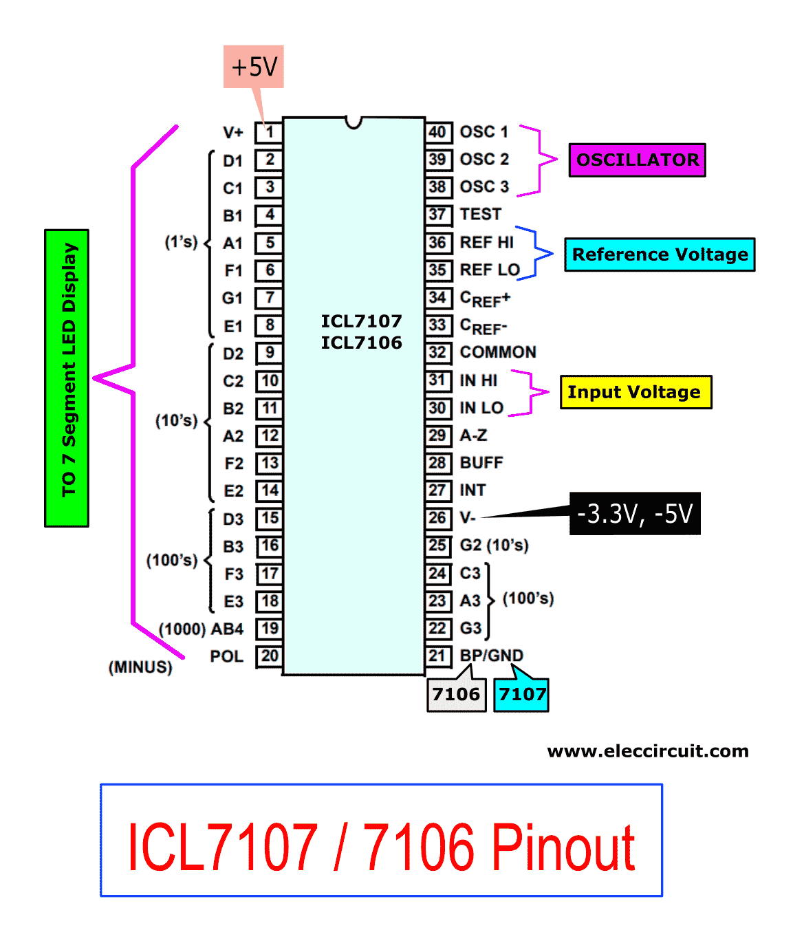
ICL7107 Pinout/datasheet
The heart of this circuit is IC-ICL7107. Now it’s incredibly cheap. In Figure below is ICL7107/7106 pinout. This IC is a 40 pin model. Which indicating the position and function of each pin is ready with important features.
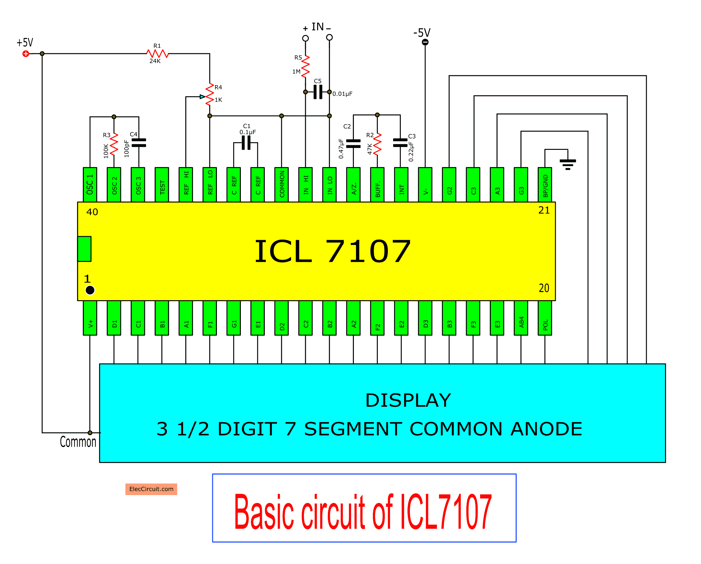
Basic usage ICL7107
Let’s look at a basic usage circuit of ICL7107 for simple applications. The value of devices in the circuit can determine 2 cases.
- The maximum range setting.
- The maximum input voltage that can measure. It will have a value to be two times of the Vref voltage.
So, if we want to measure the voltage signal that has a full scale of 200 mV. Then, we must adjust the Vref is equal to 100mV.
Or, if you want to measure the maximum range of 2 volts. We have to adjust the Vref is equal to 1 volt.
You may also like these:
- 6 ranges AC millivoltmeter circuit
- Digital capacitor meter projects easy to build
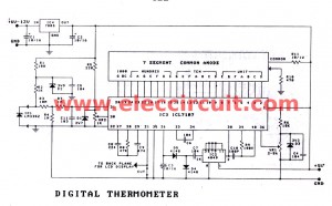
- Digital temperature meter using LM335
Clock signal generator circuit
The heart in the working of digital circuits is a clock signal. For this circuit has a suitable frequency in using are 48KHz and 40KHz
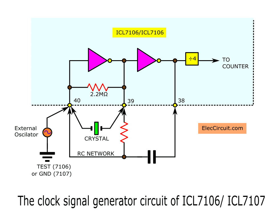
Which we have a lot of ways to make the clock signal generator circuit.
For example…
- Take a signal from external oscillator source connected to pin 40 directly.
- Use a crystal as the desired frequency, across between the pin 39 and pin 40.
- The easiest way is the RC oscillator circuit. As shown in Figure 3.We can calculate the RC from…
F= 0.45/RC
In calculation, we can change the capacitance at the desired frequency. By determining the resistance = 100K and the frequency value of 48 KHz will have the C equal to 100pF.
Read next: Based time crystal Digital Clock Generator circuit
How to choose the devices
A reference capacitor—or abbreviated as “C ref”. It is connected to between the pin 33 and 34. We use a capacitance of at least 0.1μF.
An integrating resistor (R int) Which is at pin 28 that to use the appropriate value depends on the maximum range you want. For example range 2V we use the value R = 470K, and the cycle of the maximum range of 200 mV to the R-value is 47K.
An integrating capacitor (C int) in case that we use the clock frequency of 48KHz. Should use a value of 0.22μF.
An auto-zero capacitor (Auto zero) is a capacitor. It acts to control the circuit to display is zero while without the input signal.
Its capacitance depends on the range. Such as the range 2 volts, We use 0.047μF, and in the range 200mV we use of 0.47μF.
To Generate Negative voltage
This circuit always uses three terminals of a power supply consisting of positive, negative and ground. If we use it in a laboratory, we may create a circuit is not difficult.
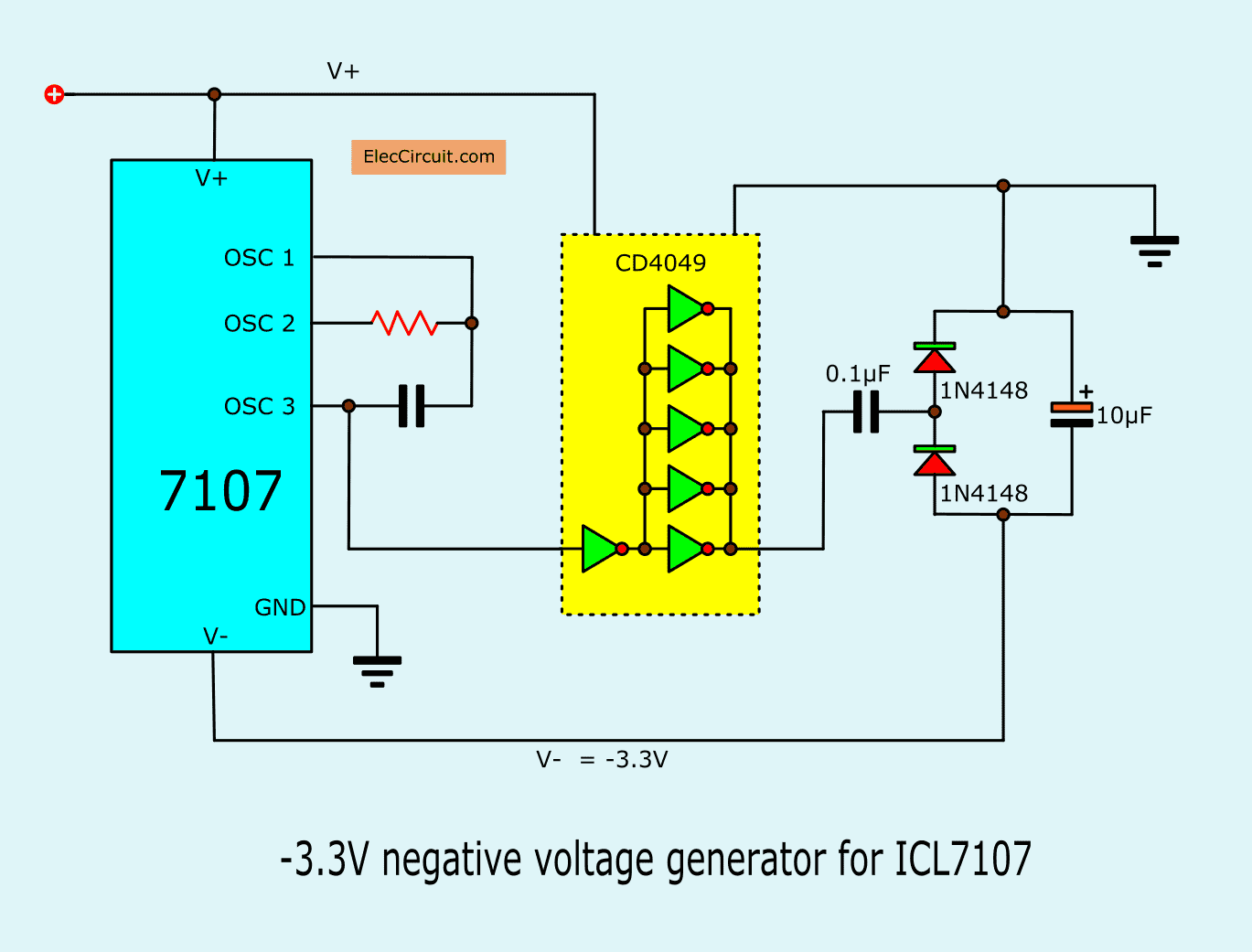
But if you want the ease of use. It may convert a battery. In normal it powers only a single positive voltage. Then, we build a negative voltage generator circuit in Figure 4.
The negative voltage generator gets a clock signal from pin 38 of IC1. Then, IC2-CD4049 inverter gate and a few components convert a signal to -3.3VDC negative voltage to supply the IC1 at pin 26.
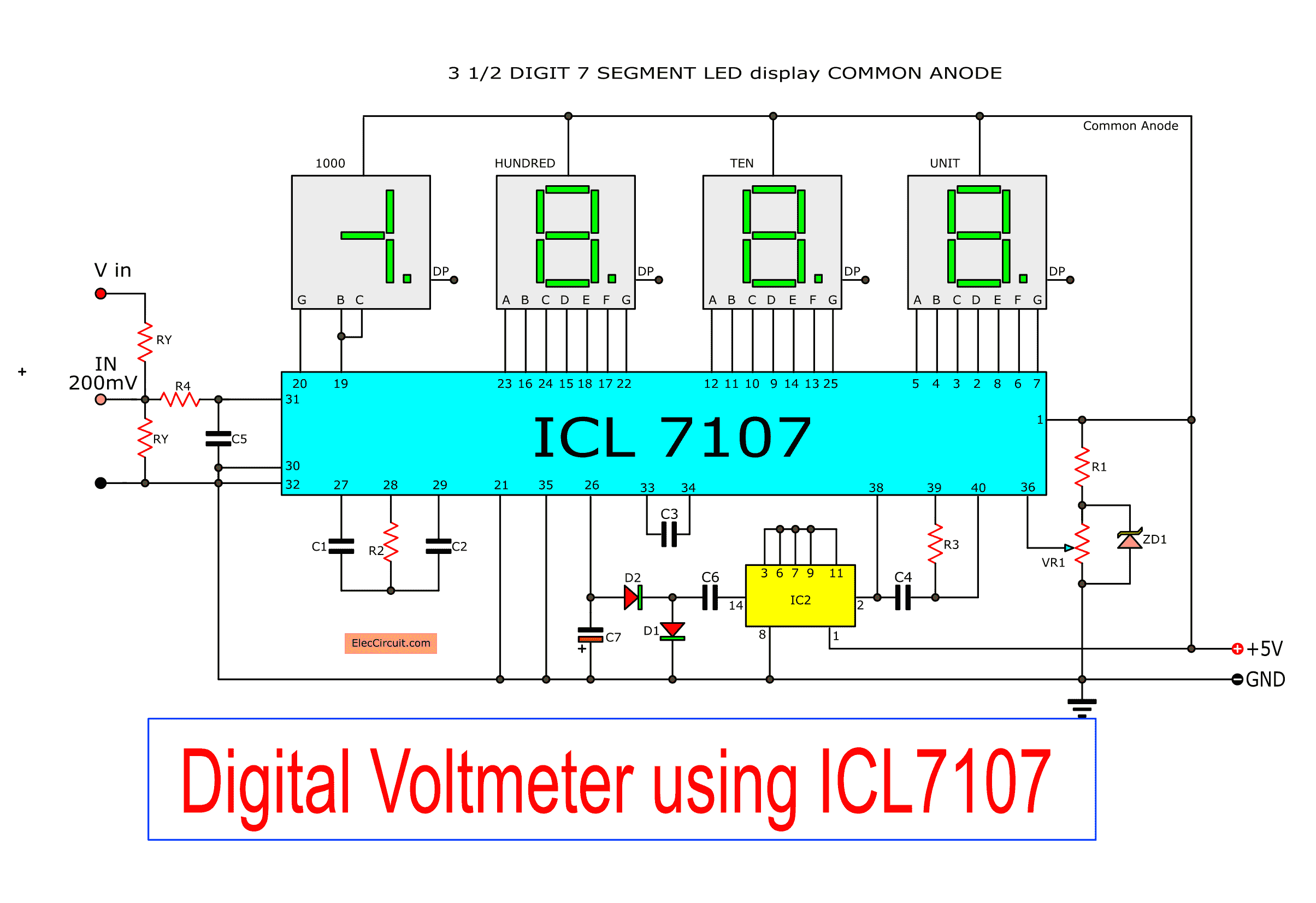
Simple DC digital meter circuit is completely
In Figure 5 is the digital voltmeter circuit designed for general applications. Which it requires the maximum range equal to 200mV.
If you want more the voltage range. Which they can do. The circuit for reducing the voltage, the circuit consists of RX, RY, calculated as follows.
RY = 2000/ (range – 0.2) K ohms …… Rx=10M
Building digital voltmeter circuit
Parts you will needs
IC1: ICL7017
IC2: CD4049, CMOS Hex Inverting Buffer/Converter
D1, D2: 1N4148,75V 150mA Diodes
ZD1: 2.4V 0.5W Zener diode
0.25W Resistors tolerance: 1%
R1: 10K
R2: 47K
R3: 100K
R4: 1M
VR1: 2K to 5K Trimmer Potentiometer
See modifying Digital 50V voltmeter
Capacitors
C3, C6: 0.1μF MKT (Metallized Polyester Film Capacitor)
C2: 0.47μF MKT (Metallized Polyester Film Capacitor)
C1: 0.22μF Multilayer
C4: 100pF Polystyrene
C5: 0.01μF Multilayer
C7: 10μF 16V Tantalum
Seven Segment LED display common Anode
Note: You may buy components at electronics stores here.
We solder the components as the circuit in Figure 6 correctly. Then, applied power to the circuit. Check the negative voltage of 5V (about -3.3V) at pin 26 of IC1.
Which indicates that the oscillator circuit is functioning properly.

.
Next, adjust VR1 until the voltage at pin 36 is equal to 100 mV.
Try connecting pin 37 (pin TEST) with the positive voltage. So, the display will show in 1888. It indicates the IC circuit is working correctly.
Next, Try short-circuit at the input, Number is displayed as 000. But If this is not shown, indicating that the AUTO zero is not working properly. You should increase the capacitance.
If everything is correct. We will have a digital voltmeter circuit with an input sensitivity of 200mV to use.
You may like these circuits, too.
1. If you are interested in this circuit.
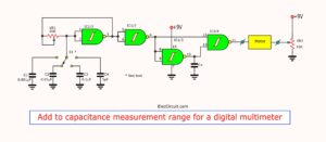
You can apply to The digital capacitor meter project
2. If you fear that it will not work. You can see the details of…
Digital LED Voltmeter Kit
3. You can look at the digital multimeter using ICL7107.
4. In the past, I used an old digital voltmeter circuit. But it was very old. You may not be able to find an IC.
5. Simple LED Voltmeter circuit using LM3914

Related Posts


I love electronics. I have been learning about them through creating simple electronic circuits or small projects. And now I am also having my children do the same. Nevertheless, I hope you found the experiences we shared on this site useful and fulfilling.
nice .. i should try this in proteus … but i hope it would works good … no errors ^_^
thanks
Hi, abdrhaman.
If you want to be sure. Please look here.
https://www.amazon.com/gp/product/B001T4RNSS/ref=as_li_ss_tl?ie=UTF8&camp=1789&creative=390957&creativeASIN=B001T4RNSS&linkCode=as2&tag=circuprojeele-20
Thanks.
hello what types are the caps used there are so many different type of polyester and polypropylene the data sheet does not specify
thanks in advance
hello ,,,,
we want to make a both ammeter and voltmeter combined with single 7107 ic …
can it be possible ..
if yes ten please help us …..
Hi manjeet singh,
Thanks for your feedback.
I have one projects for you please wait me.
Please look at: https://www.eleccircuit.com/lets-build-the-digital-multimeter-using-icl7107/
Wow i must try this. Its an amaizing project