
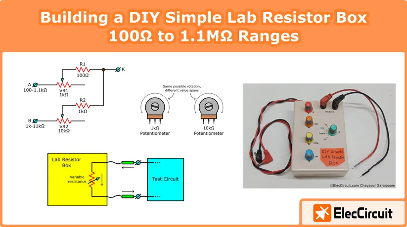
Let’s build a simple DIY lab resistor box. It’s a simple tool to test or experiment with varying resistances within a test circuit to find which works best.
A lab resistor is also a simple passive tool, meaning it’s unpowered, relying instead on the connected test circuit. This makes it easier to put together using the basic components we had lying around.
In this article, we’ll walk through its purposes, basic design, and build a functional lab resistor. We would also add some nice-to-have functions, such as a range selector and a mode switch.
The Lab Resistor Idea
A lab resistor, or resistor box, is a testing device with variable resistances, which we can use quickly for circuit testing or design purposes. A lab resistor is not meant to be a permanent part of the circuit. We only use it for basic experimentation and debugging.
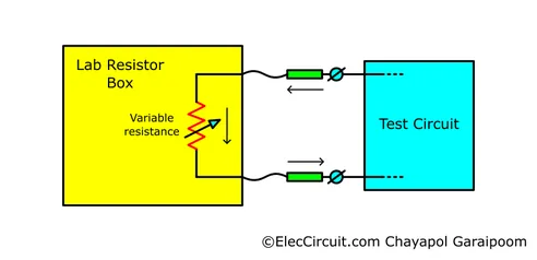
Usually, its resistance is adjusted manually using a physical knob, like a normal potentiometer, though some very advanced ones are controlled digitally.
You can also think of it as an external variable resistor (potentiometer) that can be quickly connected and disconnected from the testing circuit.
Various types and designs of this lab resistor are available as a complete product. They’re usually quite cheap because of their simplicity. Hence, we’re building one ourselves today.
Why Do We Need a Lab Resistor?
The answer is quite simple: to be able to quickly experiment with a wide and varied range of resistances in the test circuit.
For example, consider this scenario: we’re designing a transistor circuit, and according to the calculation, R2 is approximately 120kΩ.
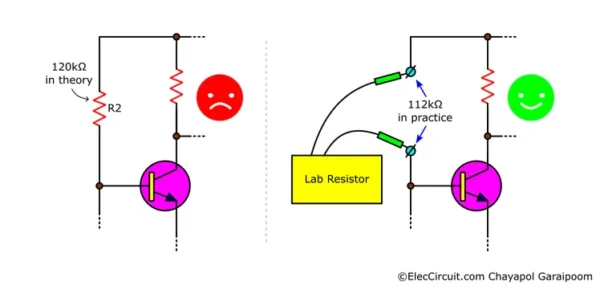
However, in practice, after we assembled the circuit on a breadboard, it did not work as intended. We suspect the actual required value of R2 differs from our calculation, and so we want to try other similar values.
Instead of going around looking for other standard-value resistors or preparing a larger potentiometer, we can just connect the lab resistor in place of R2 and quickly adjust its resistance until the circuit works as we like.
Afterward, we can measure the lab resistor’s resistance and maybe replace it with a similar-valued normal resistor later.
Let’s say that in this case, the circuit works best at around 112kΩ. Now we can replace the lab resistor with 100kΩ + 12kΩ resistors as the final solution.
A lab resistor can be a useful tool to have in cases where we want to make a quick adjustment when the real-world result does not match theory, or when we just want to experiment with different resistance values to see which works best with our circuit.
With all that said, we have a few safety concerns about this lab resistor idea we need to address, which we’ll discuss shortly.
Basic Adjustable Resistance Idea
Let’s start with the most basic idea of just one 1kΩ potentiometer—let’s call it VR1. This VR1 here has an available resistance range of 0Ω to 1kΩ.
This means we can connect this to any test circuit via the A and K terminals to produce any resistance within the VR1 range.
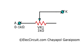
However, in practice, we don’t want 0Ω resistance in a circuit. It effectively creates a short circuit, drawing a large current through and burning the potentiometer or, worse, damaging other components in the test circuit by overcurrenting.
To prevent this short circuit, we need to add a constant resistance (R1) in series with the potentiometer (VR1), as shown in Figure 3.2. Let’s say R1 is 10 times less than VR1’s maximum value, which is 100Ω.
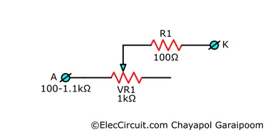
R1 will act as a constant minimum resistance when VR1 is turned to 0Ω. As a result, the combined effective resistance range of VR1 and R1 is 100Ω to 1.1kΩ. This configuration is much safer than before.
Let’s use this basic variable-resistance idea to create a resistor box by adding a few more resistance ranges and a couple of switches to help select them.
Complete Lab Resistor Box Circuit
In the end, we arrive at the circuit shown in Figure 4, which consists of the same resistor-potentiometer layout as the previous concept, just more of them. The four sets of resistance represent 100Ω to 1.1kΩ, 1kΩ to 11kΩ, 10kΩ to 110kΩ, and 100kΩ to 1.1MΩ, respectively.
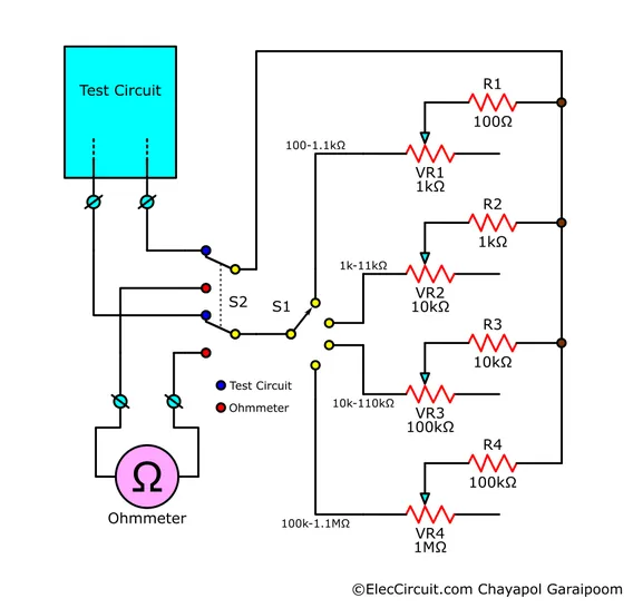
To make jumping between resistance ranges easier, we added a 4-way selector switch (S1) to choose between the four ranges.
To eliminate the need to connect and disconnect the wire between the test circuit and the ohmmeter, we added a DPDT switch (double-pole, double-throw) (S2) to the circuit, as shown in Figure 4.
When S2 is switched upward (blue), the lab resistor is connected to the test circuit. On the other hand, when it is turned downward (red), the lab resistor instead connects to a digital ohmmeter, which then reads its current resistance.
This effectively creates two separate modes: a test-resistance mode (blue) and a resistance-measurement mode (red).
Since S2 effectively creates an open circuit in the test circuit when we select the ohmmeter option, we have to make sure that doing so has no negative effects on the test circuit. Otherwise, this makes reading its resistance much more convenient.
Building and Testing
Now that we have the circuit design down, let’s build it. Since this lab resistor will be a tool we use in the future, we decided to assemble it in a proper plastic box.
However, during component preparation, we noticed that we don’t currently have a large 1kΩ potentiometer in our storage, only a small trimmer-style one. Ordering one would be expensive and would take a while to arrive.
As a workaround, we figure we can reduce the effective resistance of a larger potentiometer by adding a resistor in parallel to it. The closest we have to 1kΩ is 5kΩ, so we’ll go with that for VR1.
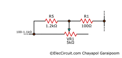
Let’s call this parallel resistor R5. To find the value required to reduce the pair’s effective resistance to 1kΩ, we simply use the parallel formula.
$$1k\Omega = \frac{5k\Omega \times R5}{5k\Omega + R5}$$
1kΩ is the parallel resistance we want, and 5kΩ is the maximum resistance of VR1. Solving for R5 yields 1.25kΩ. To make things simpler, we rounded R5 to the nearest common resistor value of 1.2kΩ, as shown in Figure 5.
With that out of the way, we mounted each component onto a plastic box and then wired them up as shown in Figure 6.1.
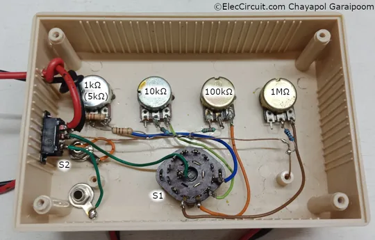
We’d also make two pairs of wire, one for connecting to a test circuit on a breadboard and another for connecting to the digital ohmmeter’s probe connection sockets.
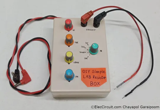
After labeling each knob, we did a simple resistance test on each range. All resistances from 1kΩ to 1.1MΩ are available across the 4 resistance ranges, with the selector switch selecting which range is used. The DPDT switch allows for quick and easy switching between the test circuit and the ohmmeter.
Conclusion
This lab resistor box serves its purpose as an external variable resistance quite well, given how simple it is. That said, it still misses some rather important features, such as overcurrent protection and higher precision. In the future, we might make a new version with these features in mind.
Want to learn more?
We’ve extended this article on Patreon (16 pages, 1858 words) with extra content, including some additional design processes.
👉 Read the extended lab resistor box article on PatreonExclusive posts on Patreon come free of advertisements and in PDF format with high-definition illustrations. Membership fees will allow us to continue to do what we do without as much reliance on advertisement. Thank you very much.
Hello. I’m Chayapol, but I could also go by Aot. I write and draw illustrations for ElecCircuit.com.
I usually cover articles related to digital electronics, logic, or basic principles or ideas on the site.