I am going to show the working of a constant current battery charger circuit. They use a few components, 7805 and some transistors. We often use 7805 in DC regulator, 5V 1A. A lot of digital circuits use them as a source. It can keep a stable voltage.
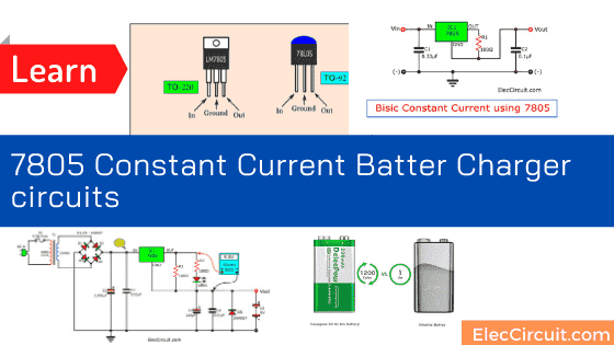
In the datasheet, 7805 has many helpful. One thing is we can use them as constant current regulation. It is so easiest and more convenient than using transistor circuits.
Because of a one-man show with a few parts. So, become easily the battery charger circuit.
So what!
Imagine you use a digital multimeter, right? Because it is highly accurate and using easy. It uses a 9-volts battery as the main energy. When we often apply it use it very consumption. It runs out of energy. You need to change to a new one.
What can you do it?
Use a rechargeable battery of 9 volts (8.4V). It is rechargeable over 200 times so worth it. But we need the right charging way.
Let me show you a nice 9V Ni-MH battery charger.
Of course, when you finished reading. You can apply it to charge any battery like 7.2V, 12V battery, and more. As your ideas.
Make Gel cell battery charger circuit
Idea circuit
Firstly, should know about this battery before, as Figure 1. More detail as follows:
#1. It is a Ni-MH type, has a lot of features:
- No memory effect. You do not need to run out of capacity. Before charging.
- High current.
- Cheap!
- And more popular for now.
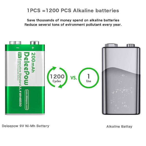
Figure 1: Example Ni-MH rechargeable battery of 9V.
If you are looking for it on Amazon. Click here
#2. Enough Energy—An output voltage around 8.4V and provided of 200mAh (applied current of 200mA within 1 hour.)
Even, just voltage is only 8.4V. But can replace a common 9-volt battery.
Because it can supply a constant current to enough to use for a long time.
#3. Current Charging—The label on it, charging is divided into 2 types:
- Standard model—with a current of 20 mA for 10 to 15 hours.
- Fast model—with the current of 50 mA for 5 hours.
All models use a voltage of about 20% to 50% or 12V to 18V DC voltage only.
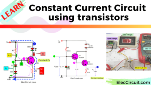
When we know enough. Let’s see the current constant circuit. Or the current regulator using IC-7805 better.
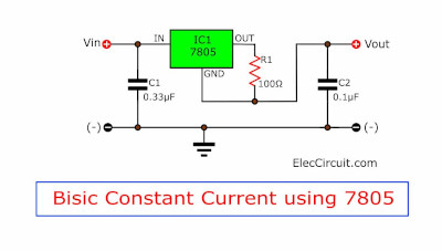
Figure 2: Basic current constant or current regulator using 7805
In the datasheet will see that a resistor-R1 passes current from a pin output of IC to load. Then, it gets the current output to pin ground, too.
The circuit inside 7805 can keep the output current in solid status. Even we change any input voltage. But do not forget it run well over 5V input.
What is more? Want to know how to find R1?
If you say yes, read below…
Recommended: Simple electronic circuits
7805 Current Regulator Calculator
You can find the current constant or current regulator calculator, below
IO = 5V / R1
Defined:
IO: the current constant output
5V: Voltage of IC-7805
R1: Resistance-R1
In this case, I want to supply a constant current of 50 mA or 0.05A.
So try some new, to find out the R1 as follows:
R1 = 5V/0.05A
= 100 ohms
Is it easy?
Practical applications circuit
When getting the concept circuit. Then, test the circuit as this idea.
Appear good results.
And, should have an LED to indicate the connection terminal of a battery.
Sure, the power to the battery, should is DC voltage.
So, newly designed as Figure 3.
When we test the circuit. It works well, use charges time for about 5 hours.
Then, measure the charged current around 70mA. It rises too many currents.
Because some current flows through LED1 and R2. Which battery don’t hot.
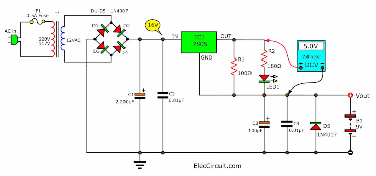
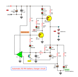
Figure 3 the real circuit of the current constant battery charger by LM7805
For other devices, You will be well familiar with F1, T1, D1-D4, C1, and C2, include is a DC power supply set. The voltage across C1 of 16V and supply it approximately 0.5A. Because of happened to I has 0.5 A transformer fitted.
Have you ever wondered why the LED is connected to the battery?
But disconnect the battery out. LED turns off.
– When trying to measure the voltage drop across R1, on without charging, will no voltage at all.
But when connecting the battery charging appears voltage drop across R1 will always have the 5V, even if we use any rechargeable battery type or short-Circuit.
___this feature, you also understand it like me, when having the voltage constant and resistance not change, so the current flowing through R1 also must stable. And current flow the output also same them.
Look at 7805 pinout
How it builds and application
For this current constant battery charger, you make the PCB as copper-layout in Figure 4 and solder all parts on components-layout as Figure 5
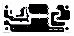
Figure 4 the Actual-size, Single-sided PCB layout
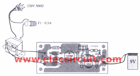
Figure 5 the components-layout
__R1 Should be calculated to fit the battery, and if the current is over 0.3A should hold the heatsink with IC1.
Figure 6 is the current constant battery charger using LM7805
The prototypes I use are the universal PCB. Because of the little devices and easy to build.
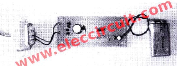
Figure 6 Application this projects
However, This circuit has a disadvantage is without a timer when finished for 5 hours and then cut off power from the battery, to protect the battery to overheat.
Components lists
IC1: LM7805
D1-D5: 1N4007, 1A 1000V Diode
LED1: LED as you need
0.5W Resistors, tolerance: 5%
R1: 100 ohms
R2: 180 ohms
Electrolytic capacitor
C1: 1,000uF 25V
C3: 100uF 25V
C2,C4: 0.01uF 100V, Mylar Capacitor
T1: 12V 0.5A transformer
Other parts, fuse, PCB, Wires, etc.
Look at others : 7805 adjustable regulator circuits
But this circuit is still not as good as its performance. Nicad Battery Charger using LM317T
and for basic: Simple Ni-cad battery charger with little parts
Related Posts


I love electronics. I have been learning about them through creating simple electronic circuits or small projects. And now I am also having my children do the same. Nevertheless, I hope you found the experiences we shared on this site useful and fulfilling.
Hmmmm good……How to know that battery is fully charged now, so that to use micrcontroller for over charging protection………..(Very basic question in mind::: How 5v can charge 9v battery when others using 12v or more for it???)
Input voltage is 16VDC….
Nice ckts
Thanks your feedback.
this doesent seem to work, put 8v into 7805 and get the same out,current is 1.5 amps!
Your first diagram is wrong. GND from the 7805 should connect to the right hand side of the 100ohm resistor…
Hello Trevor,
Thank you for your kindness. I just updated that circuit.
I hope you will help me more.
Have a good day for you.