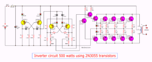
As the 200 watt inverter, Many people want to create a project of large power inverter about 500 watts. In order to use the multiple appliances at the same time. And can also be used on a large bus as a bus or coach, too.
Adding a 200watt into 500 watts is simple.We use the same PCB’s, and add the power output PCB. Large transformer is 500 watts or 40A, it can apply the energy output as needed.
Increased wattages ideas
We Increased electricity, by the same voltage, thus making inverter can apply the output power higher up. That adding the mosfet parallel to each other. And add transformer size as Figure 1.
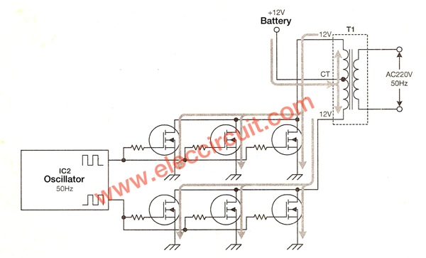
Figure 1: Increased wattages with increasing current in the circuit.
How to modify to…
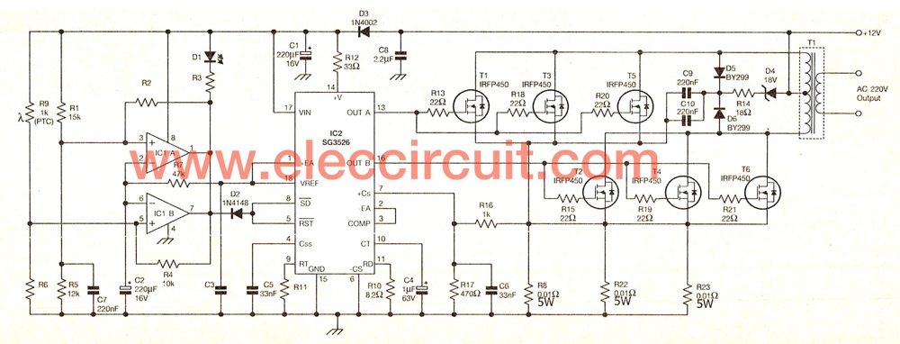
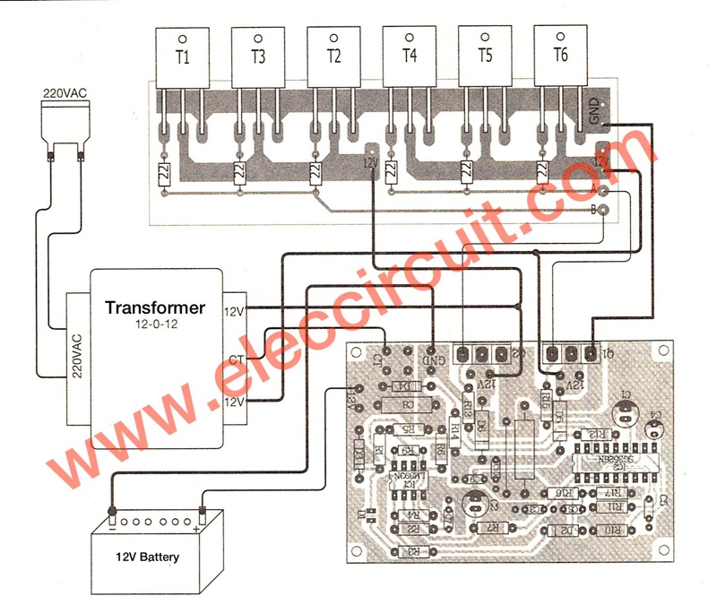
500W power inverter circuit using SG3526-IRFP540
As 200 watts inverter circuit. We use Q1, Q2 is the mosfet acts as a power output. That can withstand currents up to 18A. According to properties listed in the table of Figure 2. If the circuit is fully functional with maximum power of 12V x 18A = 216 watts. But in practice, the circuit should work up, it may be damaged. Therefore, it is designed to operate up to 200 watts.
Since we want the current more than 40A. But the power mosfet single, able to withstand current is 18A, therefore have to be 3 pcs. And When designing a circuit in a push-pull model thus requires a power mosfet 3 pairs.
We have the output current up to 54A which can withstand more demanding than 14A. It is good for the operation of the circuit. Because each power mosfet will not be overburdened. And the heat of the mosfet least, the lifetime of the life circuit.
In Figure 3 is the inverter circuit with a power output Increased at least 2 pairs and use the 12volts 40A transformer, so that the power output 500 watts.
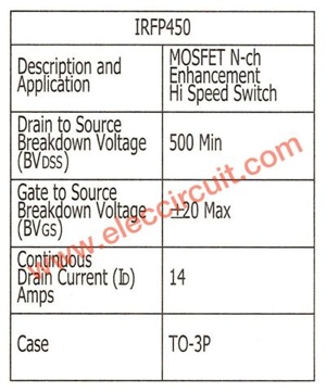
Figure 2 Table electrical properties of power mosfet – IRFP450
Figure 3 The schematic diagram of this projects
We increase the over current checker resistors from two into tree (R22 – R23 parallel to the R8.) The operation of the circuit remains the same.
We use the same PCB as Figure 4 PCB layout and components layout in Figure 5
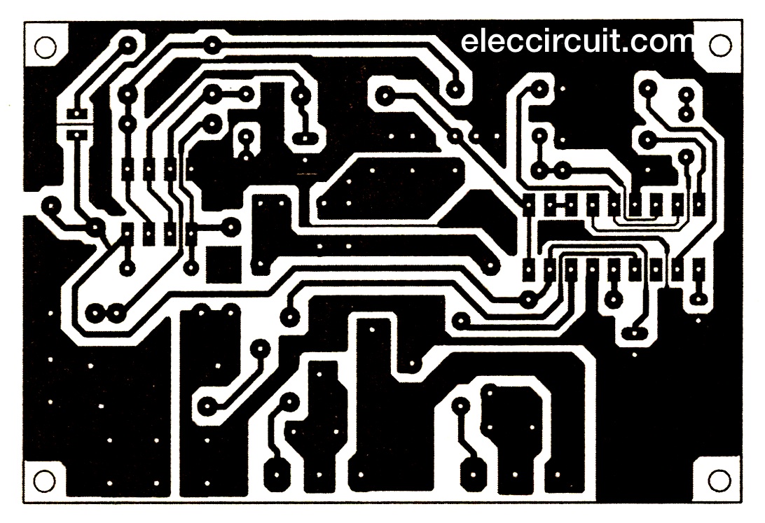
Figure 4 PCB layout of 200 watts inverter

Figure 5 components layout
We set up the device the same except power mosfet (T1 and T2). The resistors R8, R13 and R15 wired jumper instead. Because the resistance both moved to the power output PCB. As Figure 5 PCB layout
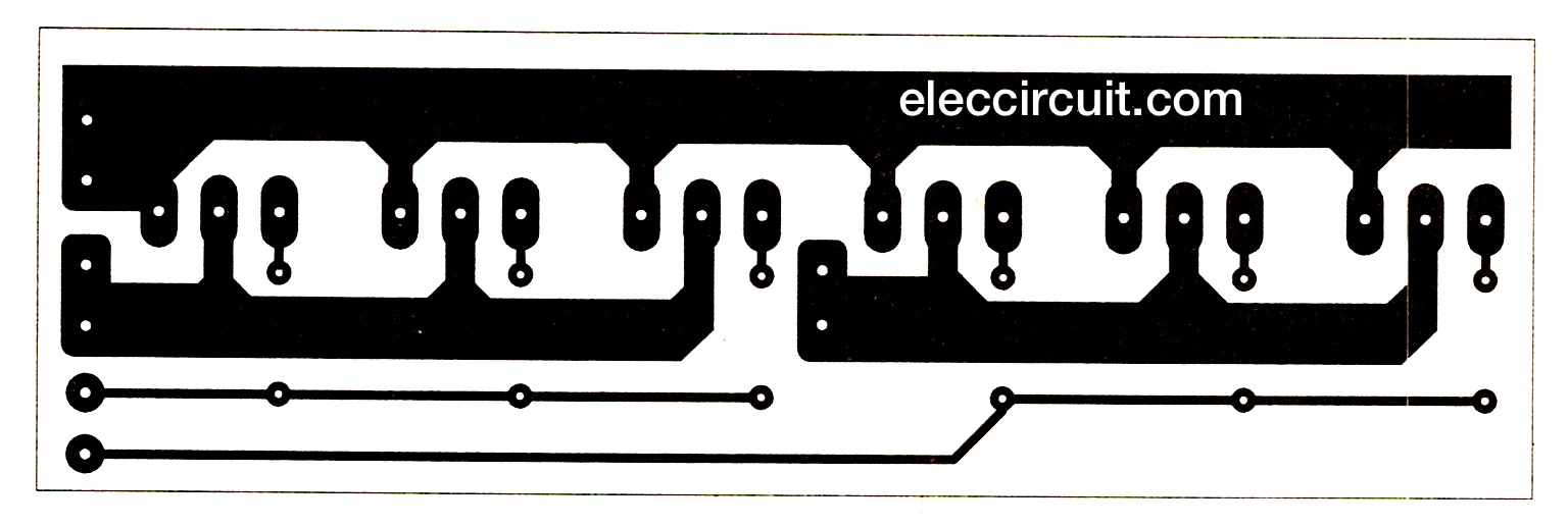
Figure 6
In Figure 7 is full components layout
Caution
Use the large wires more than about 8mm. Because it use high current load.

The parts you will need
Resistor (0.25W 1% Except where indicated)
R1______________15K_______________ = 1 pcs.
R2______________22K_______________ = 1 pcs.
R3______________2.7K_______________ = 1 pcs.
R4______________10K_______________ = 1 pcs.
R5______________12K_______________ = 1 pcs.
R6______________4.7K_______________ = 1 pcs.
R7______________47K_______________ = 1 pcs.
R8,R22,R23______0.01 ohms / 5W ______ = 3 pcs.
R9______________1K (PTC)___________ = 1 pcs.
R10_____________ 8.2 ohms___________ = 1 pcs.
R11______________16.9K______________ = 1 pcs.
R12______________33 ohms____________ = 1 pcs.
R13,R15, R18- R21_ 22 ohms___________ = 6 pcs.
R14______________ 18 ohms___________ = 1 pcs.
R16______________ 1K ________________ = 1 pcs.
R17______________ 470 ohms___________ = 1 pcs.
Capacitors
C1,C2____________220uF 16V____Electrolytic____= 2 pcs.
C3,C7,C9,C10_____220nF 50V____Polyester_____= 4 pcs.
C4______________1uF 50V________Electrolytic____= 1 pcs.
C5,C6___________33nF 50V_______ Polyester_____= 4 pcs.
C8___________2.2 uF 50V_______ Polyester_____= 1 pcs.
Semiconductors
D2__________1N4148_____75V 150mA Diodes__= 1 pcs.
D2__________1N4002_____100V 1A Diodes__= 1 pcs.
D4__________18V 1W_____Zener Diodes___= 1 pcs.
D5,D6_______BY299______Didoes__________= 2 pcs.
IC1_________LM393N____op-amp IC________= 1 pcs.
IC2_________SG3526N or SG2526N IC______ = 1 pcs.
Q1-Q6______IRFP540 mosfet______________ = 6 pcs.
D1_________LED 3 mm red or as you need____ = 1 pcs.
Other parts
T1________220V / 12V-0-12V / 40A transformer__ = 1 pcs.
PCBs,Heat sink, wires and others.
See more: The inverter circuits
Related Posts
I love electronic circuit. I will collect a lot circuit electronic for teach my son and are useful for everyone.
Thanks for info.
Which cad Software you are using to produce the pcb layout.
Hi Salim Khan
Thanks for your feedback.
ooooooooooookkkkkkkkkkk
Hello friend I am I put 500 watts MOSFET power inverter using SG3526-IRFP540 but I have a problem with the resistors 0.01 ohm 5 watt no room to 3 resistors there is only 1 place. And diodes D 2 D. 3, do not know ?? . And c 8 2.2 uf polyester or electrolitique. I would like a quick answer thank you very much. moris.
Hi Akhil Joseph Dious
Thanks for your feedback.
I don’t know for this project. But normally I use eagle for small size projects.
Hi Moris azoulay,
Thanks for your feedback.
I’m sorry this project I not tested it.
You can do this with only one pair of mosfets
no need for parallel mosfets.
you can use mosfets rated on 200Amps current
i use this only one pair of mosfets in inverter circuit for 2000 Watts.
https://www.alldatasheet.com/datasheet-pdf/pdf/564882/TI1/CSD19536KCS.html
Great! Its almost perfect but there’s some error
There’s two D2 on materials list I think you mean D1 but I don’t know which of those two is D1..
And at the center of diagram there’s a part without label, can you please tell me what’s that??
That’s all hoping for a quick response and thanks in advance 🙂
I know nothing bout these kind of thing and I’m
Just trying to learn by researching and these page is the most detailed and helpful for me that I ever found 😀
thanks for sharing these knowledge 🙂
Thank you very much for your precious answer! !”! I really appreciate it! -_-
Transformer required in project is for input or output?
And how much required battery ampere hour?
your project are magnificent ,we want to make it,But we lack parts,especially high power transistors.how do we find parts
Hey…. Please give me the working of this project.
This project is good for Electronics enthusiastic people; here I would like to know how to I converted this inverter to uninterrupted power supply (UPS) for my Computer.
Can i use 3A transformer?
Hello, i can not find R8, R22 and R23 (0.01 ohm) in the power pcb of the 500w inverter.
gr Auke Hoekstra, Holland.
Dear Bro,
I have a question how do we charge the battery. Do need to add up a charging circuit fo the battery.
Will the same circuit will charge the battery, and automatically i will turn from power source to battery when no supply.
Hola me pueden decir cuanto podría cobrar uno por este proyecto
Obra de mano también cuanto
mohammed aslam you don’t have to use the same inverter to charge it’s battery, you have to provide a power source from solar collectors or you use NAPA light (or generator) with a transformer ratio of 450:40,the transformer will produce 25V in 200V power supply, so you have to regulate it to 15 volt with diodes,capacitors, and LM2815 voltage regulator an use it to charge the battery. But you can still use any transformer with any ratio as long as it produce up to 15… volt.
For more info contact [email protected]
please sir, I made this project but the problem am having right now is that when there is no transformer connected, I will measured 12 V from the drain,source and gate of the MOSFET but when I connected the transformer, I will measure 0V from drain, 12V from gate and source, which result in short down. I don’t really know weather it is couse by some modifications I did to it! Here’s the modifications :
(1) I used IRFP150 and I added one IRFP250 because I couldn’t found all the IRFP 150
(1)I use 4A battery just for testing
please I need help form anybody here. Email:[email protected]
Hi sir, I’m having a problem right now with this project. The problem is when the circuit is connected to the transformer, there is no output measured. Although I measured 12v from the circuit before connecting it to the transformer. What might be the possible solution for this sir? Ty
Hi every body i’m new to this site web, and i have a question for you. my question is…in the figure 7 we have 6 transistors IRF540, and the figure 5 we have 2 transistors Q1 and Q2 i doesn’t see what kind of transistors…cuz you don’t mentioned us.
Thanks for supporting Electronics Engineering.
please can sg3526 be used as feedback voltage like sg3524
pls what is the wave form of this inverter
2 step square wave output. Most “modified sine wave” inverters sold today are 3 step square wave.
Hi Sir. I don’t know where to place R22 and R23( the 5Watts)
I also need to know what you mean with….The resistors R8, R13 and R15 wired jumper instead.
I dont know much about electronics but id love to complete hid project.
size of the two pcb plz
what is R1 ??? KK?