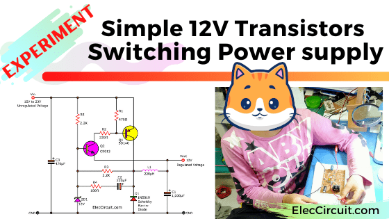
Can we build a switching power supply with 2 transistors? Yes, we can! Let’s experiment with a simple 12V switching power supply circuit using transistors.
The 12V switching power supply circuit can be created in many ways. Nowadays popular way is to use IC because of its convenience and high efficiency.
However, this circuit we are making consists of the transistor and a few parts. Because we want to make great use of old and common components in our inventory.
How simple transistor switching power supply circuit works
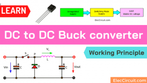
Look at the circuit below it is the design of the simple switching regulator circuit. It is a step-down DC converter or Buck Converter to convert the input voltage from 15V to 20V to the output voltage of 12V.
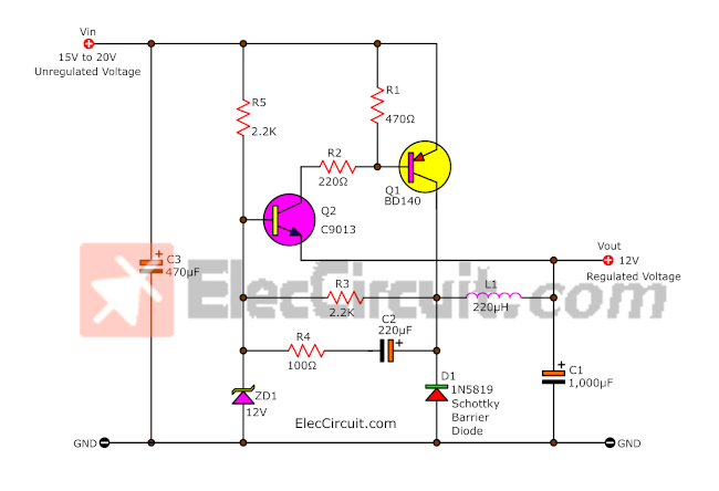
Simple 12V switching DC regulator or step-down converter circuit
The important component Q1(BD140) acts as switching and has common the main components is L1, D1. Both transistors, NPN+PNP act as feedback to each other. To generates the frequency or to work as the switching continuously. But this circuit, the current of the coil is not maximum. Because there is a voltage detector or error sensor with C2, R4, and ZD1 12V Zener diode to control the voltage to be constant.
When we apply a DC input voltage to this circuit, causes the transistor Q2(S9013) to get a biased current. Because the current flows through R5 to bias the Q2 into the current conduction and impact to the Q1.
The Q1 has the current flow through the emitter to the base to send the current pass through the conduction of Q2.
This case therefore equivalent to Q2 a unit to control bias Q1. It makes Q1 apply current to the collector to the L1 coil.
But since the base of Q2 has a fixed reference Zener diode (ZD1) to keep the constant voltage at 12V.
When the output voltage rises up to 12V, causes the voltage across the emitter of Q2 is also higher because it is at the same point. The result is Q2 turns off not conduct the current, therefore Q1 stops conducting the current too.
Now the coil will start providing current. To accumulate at C1 with a rectifier D1. And when compared an electrical potential to ground. To the left of L1 negative voltage and the current of L1 have gone. Working new round will occur.
If we consider this system found that the performance of this circuit is quite more than 90%.
Read also: How to use 7805 voltage regulator
Parts list
To start this circuit, you need the following parts:
Semiconductors
- Q1: BD140 or equivalent, 80V 1.5A, TO-225 PNP Transistor
- Q2: S9013 or equivalent, 40V 0.5A, TO-92 NPN Transistor
- D1: 1N5819, 40V 1A, Schottky Barrier Diode
- ZD1: 12V 0.5W Zener Diode
Electrolytic Capacitors
- C1: 1,000µF 25V
- C2: 220µF 25V
- C3: 470µF 35V
0.25W metal/carbon film Resistors, tolerance: 5%, (Unless stated otherwise)
- R1: 470Ω
- R2: 220Ω
- R3, R5: 2.2K
- R4: 100Ω
- L1: 220µH Inductor
Read first for beginners: How do transistor circuits work
You may also like these, too.
- 3.7V to 5V Boost/Step-up DC converter circuit using MC34063
- Simple 5V Switching Regulator circuit using transistor
- 1.5V to 5V boost converter circuit for microcomputer
- USB 5V to 12V DC-DC Step-Up Converter circuit
- Simple 6V to 12V boost converter circuit using BD679 transistors
Related Posts

I love electronics. I have been learning about them through creating simple electronic circuits or small projects. And now I am also having my children do the same. Nevertheless, I hope you found the experiences we shared on this site useful and fulfilling.
Hi !
Great job you’ve done. Can you explain to me the purpose of R3,R4,C2. Its not very clear to me.
Thank You
what’s function of R3, R4 & C2? i tried remove them and then the circuit still work well.
is it step-down circuit or just linear circuit?
is bta43 typographical error? can i use schottkey bat43 for the diode? or is there any alternative for bta43? thanks!
This is my feedback after tried out the 12V output switching regulator physically. I replace the inductor value from 220uF to 220uH.
Observations:
(1) it is a linear 12V regulator at quiescent state, when resistive loaded it become a relaxation oscillator and not a switching regulator.
(2) a switching regulator has switching format change to compensate load variance that this design is missing, such as PWM, PPM or the like.
This has prompted me to build test my own self reg. with a complementary pair.