When we need a small-sized high-efficiency power supply, most people would pick a Switching power supply over a Linear power supply. In the past, I liked a Linear power supply. But sometimes it is better to try something new.
In this post, we will learn what switching and linear power supplies are and how they work.
Maybe after reading this article, you will like it as much as I do.
How many types of power supplies are there, and what are they?
The power supply is the source of energy for various circuits. It will convert the AC mains into DC voltage. At a fixed or variable voltage as required for your work.
There are two main types of power supplies:
- The Linear power supply is widely used. It is simple because circuits are not too complicated. But they are large and low-efficiency, at only about 50% or more. While they work, most energy lost is in the form of high heat.
- Switching power supply is commonly used at present. Because of its small size, high efficiency at about 85% or more. Assume we put in 100% electrical energy. And it is transformed into 85% energy for the load. With 15% lost energy in the form of heat.
But the switching supply circuit is quite complex. Previously, I tried to avoid it because I wasn’t sure if I could explain it in a way that was easily understood.
Ready to get started?
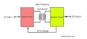
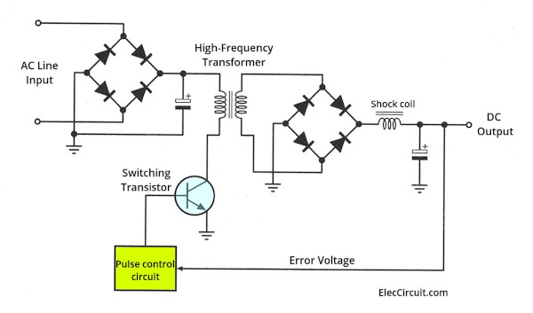
We should start by looking at the block diagram of the switching power supply. Although the circuit structure looks complicated, if we separate it into parts, it can be easier to understand.
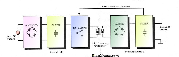
The highlight of this circuit is that it works at a high frequency. Therefore, it has a smaller transformer, but said transformer has to be a high-frequency switching system type.
The input and output of the circuit include the rectifier and filter circuit. At the output, there is an error voltage detector to stabilize the output voltage.
Of course, now you may not understand it all. But when you read the next section, you will understand more.
What’s more,
The Rectifier AC to DC—Simple but Helpful
The switching power supply will have the rectifier circuit at both input and output. Most of this is a bridge rectifier circuit.
The part that converts AC (Alternative Current) to DC (Direct Current) is called a Rectifier. In a linear circuit, this part is important. In the switching supply circuit, the rectifier circuit is also important.
The important component is the diode, which is a type of semiconductor that allows current to flow through it only in one direction and out the other direction. In the process, any Alternative Current (AC) that flows through will also come out in the form of a Direct Current (DC).
Then, the result DC will flow through the filter to smooth up the current.
Recommended: How Rectifier circuit works
In a switching power supply, there are four types of rectifier circuits:
1# Bridge Rectifier—AC main to DC pulse
Normally, we will find this rectifier circuit at the input side of the switching power supply as in the circuit diagram below.
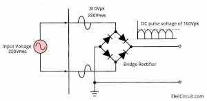
The input AC voltage is 220V RMS or 311 Vpk, which is then rectified to a DC pulse voltage of 160Vpk. Then, the DC pulse passes through to an RF switch circuit.
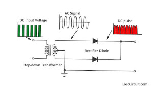
2# Half-wave Rectifier for RF AC Signal
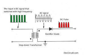
In a switching power supply, the input DC signal will be switched with a high-frequency RF signal. Then, the step-down transformer transforms it into low-voltage AC. Next, it flows through a half-wave rectifier to be rectified into a DC pulse.
3# Full-wave Rectifier using Center Tap Transformer
This is a step up from a half-wave rectifier. We will often see a rectifier like this. And, notice that it uses the center tap of the transformer’s secondary coil. It also connects to the ground as a reference.
4# Full-wave Bridge Rectifier after a Step-down Transformer
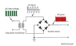
This circuit does not need a center-tap transformer; instead, we need to use two more diodes.
Selecting Diodes for the Rectifier Circuit
There are two important factors, which are:
The Peak Inverse Voltage—PIV, for short
It is the maximum voltage that the diode can tolerate. While it receives a reverse bias or while the diode is inactive.
The PIV value of the diode used should withstand at least two times the operating voltage. And for safety reasons, it should be increased by about 50% as well.
For example,
At an AC input voltage of 220Vrms, the peak voltage is 1.414 x Vrms = 311Vpk.
We should choose a diode with a value of:
PIV = (311Vpk x 2) + (311Vpk x 0.5)
= 777.5VPIV
Forward Current—IF
It is the current that the diode allows to flow through it when receiving a forward voltage without being damaged. And more importantly, do not forget to increase it by about 50%.
For example, an input rectifier circuit with a current of 1A.
We should choose a diode with a forwarding current of:
IF = 1+ (1 × 0.5) = 1.5A
Why is the Filter so Important
The voltage from the rectifier is DC. But we cannot use it yet. We need to smooth it with the filter capacitor. Both linear and switching power supplies need to use these filters.
The capacitor is a component used to store energy. It charges up the DC pulse voltage within it until it reaches its maximum capacity. And then it will release the stored energy when there is a load.
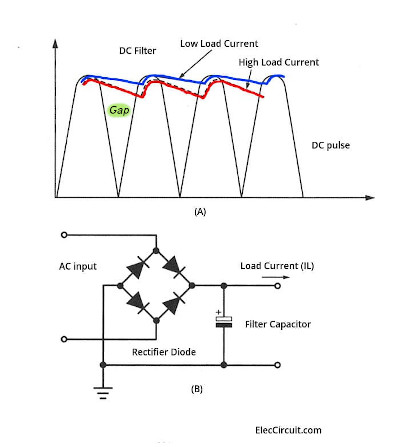
The (A) signal graph shows the filter effect of the capacitor. When the waveform reaches its highest point, the capacitor will charge up. Then, the waveform will start to drop. At the same time, the capacitor will discharge, filling the gap between each highest point of the waveform.
Note that this is not perfect. When connected to a heavier load, the capacitor discharge cannot keep up with filling the gap anymore.
Causing a ripple across the top of the waveform, called the Ripple Voltage.
- There is a high ripple if the load current is high.
- In contrast, low ripple if the load current is low.
And if we take a look at the block diagram (B). It is a normal filter using an electrolytic capacitor.
Read next: How to design the unregulated power supply
If we want to lower the Ripple Voltage. We can increase the capacitor’s capacitance or add another capacitor in parallel to the original one. To lengthen the discharging time, resulting in higher gap-filling capacity.
Picking the capacitor for our voltage range
Importantly, we need to use a capacitor with a voltage rating of approximately 50% or higher than the circuit currently uses.
For example, a 12V circuit would need at least a 25V capacitor.
High-frequency Transformer
A transformer is a component that is used to convert a high voltage on a primary coil into a low voltage on a secondary coil. As in the illustration below.
It is one of the ways to connect the transformer with the input and output. When we use it on the switching power supply circuit, we would need a transformer with a high frequency of 20 kHz or more.
Typically, the commonly used 50 Hz transformers will not be able to be used at high frequencies.
Although the size and shape of the switching transformers are different from the normal 50Hz transformers, they still use the same basic principles of magnetic field coupling as a normal transformer.
The high voltage is connected to the primary coil and it will store energy and create magnetic fields alternating between the On and Off phase.
The transformer core will act as a magnetic field, inducing the secondary coil in the form of a coupling transformer.
5 Different types of RF Switching Regulators
The heart of every switching power supply is the RF Regulator. Also known as the “Switching Regulator.”
Pulse Width Modulation Switching Regulator
Although there are many different switching circuits. But the most common one used is PWM (Pulse Width Modulation).
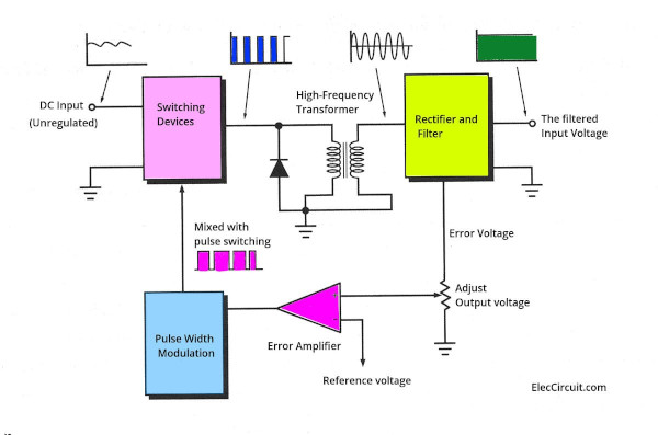
This is a basic block diagram of the Pulse Width Modulation (PWM) switching regulator. It maintains the voltage level in a closed-loop form.
To get a constant output voltage. This circuit will detect the voltage error. This error signal is used to control the pulse width of the switching circuit. By changing the pulse width of the oscillator circuit within the regulator.
The changed pulse width from the oscillator is sent to drive the transistor, which acts as a switch. Therefore, the changing pulse width causes the average voltage of the output to change accordingly.
Then, the high-frequency transformers lower the voltage into the AC signal, and it is rectified and filtered again in the rectifier and filter block.
After that, it will output a DC voltage. But some of it will be picked out as an error signal. Until resulting in the constant voltage as needed.
Which means the circuit will operate in a closed loop. The output voltage is continuously controlled until it outputs voltage normally.
Now we know the basic working principle of the switching regulator. So what next?
Read Also: 0-45V 8A DC switching power supply circuit
Hybrid Switching Regulator
It is not always necessary to use a High-Frequency Transformer in a Switching Power Supply.
Normally, the transformer is used to change the pulse voltage from a high voltage to a lower voltage.
If a DC input voltage is close to the actual operating voltage, the high-frequency transformer is not necessary.
We can use the 50Hz step-down transformer to reduce the voltage. Before feeding it to the input of the rectifier circuit.
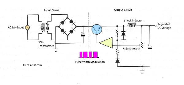
The circuit is a Hybrid Switching Regulator. Note that the input of the circuit has similar characteristics to the linear power supply. But with improved performance.
Recommended: DC to DC Buck converter working principle
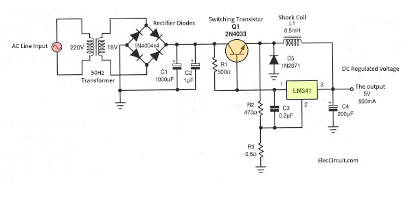
Hybrid Switching Regulator 5V 500mA
The schematic below shows the actual usage of a 5V 500mA Hybrid Switching Regulator. In the circuit, it uses NS’s LM341. Generally, it acts as a 3 Terminal Positive Voltage Regulator.
I do not like to read the text. Instead, I prefer to learn its operation from the actual circuits and block diagrams. Are you the same as me?
Let’s look into the circuit. We will understand it more.
There is also an oscillator in this circuit. Its frequency is determined by the resistance ratio of R2 and R3.
The output voltage is fed back via the inductor L1. The transistor Q1 serves as the high-frequency switching device of the circuit.
Check out these related circuits, too:
- Experiment of 5V Buck Converter Circuit Using Transistors
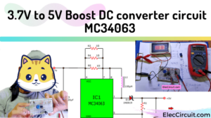
- 5V 2A Buck converter circuit using KA34063
- 12V 3A Switching Regulator circuit using LM2576-12
- Simple 12V transistor switching power supply
- LM2678 – 3.3V, 12V, 5V 5A switching fixed voltage regulator circuits
Learn how Flyback Switching Regulator Works
If you need a switching regulator that uses a few components, and your load requires a power of under 100 watts.
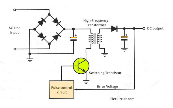
The high-frequency transformer is very important in this circuit. Because it has 3 main functions that we need, which are:
- Reducing the voltage.
- Separate the input and output circuits.
- Limit the AC line current.
Also, the primary and secondary coils are wrapped in opposite directions.
When there is a pulse control signal to bias a transistor, it will run. Driving the current through a high-frequency transformer.
In contrast, when the transistor is off, the primary coil voltage will reverse back from the coil itself. This resulted in a flyback current flowing through the rectifier and a filter at the output. We can control the pulse width via the transformer, to keep a constant output voltage.
The flyback switching power supply has a power limit rating of 100 watts. Because of the transformer’s current and the limit on the peak current that the switching transistor can handle.
For applications over 100 watts. We will use other switching regulator circuits. This will be explained in the next few circuits.
Hand-picked related circuits you may want to read:
- Cheap 6V battery charger circuit—uses a flyback switching principle working.
- 3 High Volts power supply circuits ideas
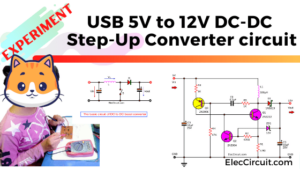
- 5V to 12V boost converter circuit or higher using transistor
Forwards switching regulator circuit of 80 to 200 watts
It is capable of delivering a high power of 80W to 200W. It can lower a ripple better than any other type of switching regulator. Because it uses a bridge rectifier circuit, which is superior to the half-wave rectifier in the flyback switching regulator in lowering ripple.
In addition, we can reduce the ripple even more by connecting a shock coil (inductor) in series with a capacitor filter.
Simply speaking, when a transistor receives a bias current, turning it on. Letting current pass through to the output of the circuit.
When a transistor turns off, the current will stop flowing to the output rectifier. The voltage across the shock coil will reverse polarity. And supplies it to a load. This is why the ripple is lower.
There is a slight difference in the pulse control circuit of this circuit compared to the flyback switching regulator circuit.
In practice, it is necessary to change the pulse-timing of the output to suit the different output sizes. For the best results.
Here are a few related posts you might want to read:
- LM2575 circuit Simple switcher 1A step down voltage regulator
- 12V stable battery voltage regulator circuit using MC34063
- 5V 3A switching power supply by LM2576
Push-pull Switching Regulator
If you need a power of more than 200 watts. This circuit is designed to be able to provide power of up to 600 watts.
It consists of two Pulse Width Modulation Switching Regulators working together to drive the switching transistor on each side.
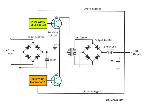
This type of circuit can drive more current.
The ripple in the push-pull switching circuit can be reduced. By balancing each pulse-wide modulation.
Typically, push-pull switching circuits have the least ripple. When compared to other switching power supply circuits.
Both the pulsed modulation and switching circuits are the same. And the point at which both circuits receive error voltage from the output has to be the same.
Conclusion
The disadvantage of a switching power supply is the RF signal noise. Which can propagate and interfere with other circuits. If not well shielded.
Regulation and Ripple values are similar to linear circuits.
In summary, a switching power supply is suitable for applications requiring small size, high efficiency, and low heat output.
Download This
All full-size images and PDFs of this post are in this Ebook below. Please support me. 🙂
Also, here are a couple of related posts you should read, too:

Related Posts

I love electronics. I have been learning about them through creating simple electronic circuits or small projects. And now I am also having my children do the same. Nevertheless, I hope you found the experiences we shared on this site useful and fulfilling.