There is 3 Temperature detector circuit for home use or cars. You are boiling hot water. How it alarms when 40 degrees Celsius. You should build the simple temperature detector circuit diagram with a buzzer alarm. It can check a changing of temperature. It is so real easy project.
Also, you can apply them to various temperature detectors. For example
Heat – cold water and many others. Follow imagine yourselves.
Temperature detector circuit with buzzer alarm
How does it work
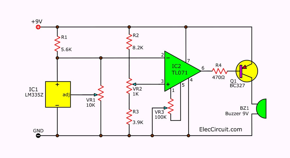
Figure 1 shows the circuit diagram. In circuit has main components.
- LM335Z is a good temperature sensor IC.
- TL071 is a comparator op-amp
- Alarm with Buzzer.
First of all, R1 limits the current to about 1 mA to IC1(LM335Z).
The temperature detector circuit diagram
Then, VR1 adjusts an output voltage to pin 2 (inverting) of IC2.
While, the R2, VR2, R3 are the reference voltage to the comparator at pin 3 (non-inverting). Both resistors R2 and R3 are a voltage divider. And the VR2 adjusts the voltage or the sensitivity of the temperature detector.
The voltage across VR2 is in a range of about 2.8 to 3.3V. Which it is comparable to the temperature range of about 268 to 337 degrees Kelvin, or -5 To 64 degrees Celsius.
You can set the temperature according to want. Since the temperature sensors IC1 can apply from -40 to +100 degrees Celsius.
For VR3 adjust the offset voltage of the input to IC2 (TL071C). To get the output voltage at pin 6 is 0 volts. When input voltage at pin 2 and pin 3 is the same value.
We come back to see it works.
When IC1 detects a temperature less than the VR1 setting. It makes the input voltage at pin 3 more than the voltage at pin 2.
Thus, the output voltage out of pin 6 to be high, to close about 9 volts. This causes Q1 to switch off and buzzer will sound off.
If the temperature starts into higher than the preset value. The voltage is at pin 2 will be more than at pin3.
Thus, the voltage at pin 6 is lower or around 1.3 volts. This causes Q1 to works and buzzers emit loudly.
Keep reading:
- Temperature controlled on-off relay circuit using LM393
- Simple Variable power supply circuit 0-30V 2A
- Full Wave Precision | Half Wave rectifier circuit using op-amp
How to build
We assemble all components on a universal PCB as Figure 2. Since it is fast and saving our money. Also, you can apply this to design a good PCB layout.
But this a little project, you can do it.

Figure 2—the components layout on the universal PCB.
The component lists
Resistors size ¼W +5%
R1: 5.6K
R2: 8.2K
R3: 3.9K
R4: 470 ohm
VR1: 10K POT trimmers
VR2: 1K POT trimmers
VR3: 100K POT trimmers
The semiconductor
IC1: LM335Z
IC2: TL071C
Q1: BC327
Others
Buzzer 9V
Battery 9V with terminal
The universal PCB
Car overheat alarm circuit
This is a circuit sound alarm when an engine start spreading the heat. Although every car will have a temperature gauge. But in some cars. May be no warning if the engine is overloaded with heat. Or the driver may not have noticed the temperature gauge can cause problems.
The working of circuit

See The circuit above:
When the temperature of the engine increases. The resistance of the thermistor decreases. Thermistor is connected to R1 for divide the voltage of the power supply to pin 2 of an op-amp IC1-LM741.
This voltage will decrease as the temperature rises, by at VR1-100K is used to adjust a reference voltage at pin 3 of IC1. When a voltage at pin 2 lower than pin 3, IC1 will be switch close makes has voltage at output pin 6 to send to IC2.
The IC2 is connected as an astable multivibrator to the sound signal generator circuit Temperature level to cause the sound can be adjusted with VR1. The VR2 will determine the frequency of the sound.
The thermistor used in this circuit, as beads. Has a negative temperature coefficient.(NTC) Thermistors are devices that are heat resistant and can pass it quickly. Suitable for adoption. Used in this circuit currents up to 10 mA.
The parts list
Resistors
R1: 4.7K
R2: 22K
RTH1: Thermistor NTC type
VR1,VR2: Variable resistors _100K
Capacitors
C1: 0.01uF 63V Polyester Capacitor
C2-100uF 16V Electrolytic Capacitor
The semiconductor
ZD1: Zener diode 5.1 volts
IC1: LM741 Op-amp
IC2- NE555 timer
Others
Loudspeaker 8 ohms
Automobile heat Warning with LED

This circuit sets up in its automobile will perform to warn give testimony know before your car be overheated too much.
By using the main part electronic be IC 741 and Thermistors. By have LED Flasher with the usual rate.
When the temperature arrives at location value keeps with before VR1. Then the temperature increases continuously LED as a result of light up. By control, checking temperature has with VR2.
This circuit gives with a power supply of an automobile has normally for the frequency of winking can fix with C1.
You can see the detail adds in the circuit.
Keep reading:
Related Posts


I love electronic circuit. I will collect a lot circuit electronic for teach my son and are useful for everyone.
will this project on bread board
It’s a pity that such a poor English makes this website almost useless
Hello Garouda Hanouman,
Thanks for your feedback. I will rewrite all article.
I hope you come back to visit my site again.
does TL071C(or TL081C,TL082C etc.) work under 273,3 degrees Kelvin? This information important an another circuit for me.