Imagine we want the automatic sound switch controller. We called the sound activated switch. It has many ways to do these circuits. But now I am going to show you three circuits ideas. I try to combine circuits that are easy for you. And hope you get a benefit.
Sound activated switch
This is Sound activated switch Circuit with PCB using IC-1458 and SCR-C106D. It will work only if the loud is overdue. Ideal for player cameras Or you can bring it to other users.
It’s not Fouls, such as You may also be applied to a Burglar alarm circuit effectively, or applied to the alarm clock, when it has sounds high level. It operates using electricity tools.
The working of the circuit
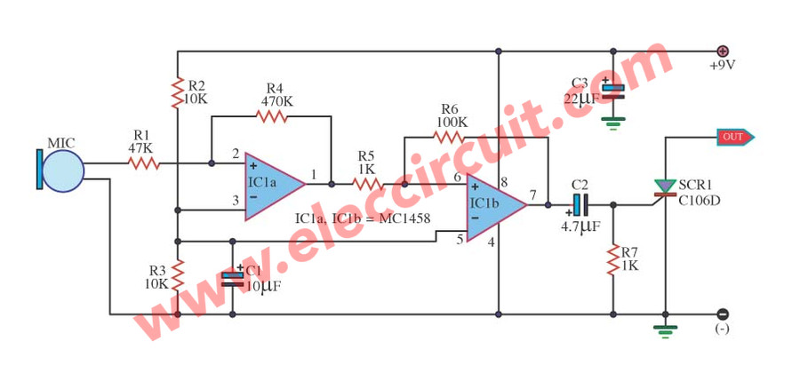
Sound SCR Switching circuit using IC-1458 and SCR-C106D
When you see advantages its, Might be a good idea now, come look the function of this circuit. As figure shown below. The sound signal is received by the condenser microphone Into the sound signal amplifier circuit That we choose IC op-amp No. MC1458 is Dual OP-Amp IC 8-DIP ST
Or other alternatives:
LF353 is IC Dual Low-Noise JFET OPAMP 3 MHz 8-pin DIP that better quality.
TL072ACP is IC Dual J-FET Op-Amp 8 Pin DIP that cheap and well.
Because the internal structure of the two op-amps, by the shape remains the same IC-741 which the op-amp IC is timeless. Make us cost-effective, convenient, and economical with space.
Come see the circuit to continue. The first op-amp IC1a is designed to gain about ten times, the output of IC1a will enter to pass the R5 to pin 6 of IC1b, that it is designed to gain about 100 times, So the all gain of this circuit is equal to 1,000 times.
The output from IC1b be fed through C2-4.7uF to trigger at pin G of SCR1-C106D works Immediately
Do you know: How SCR works
We use this circuit with the battery 9V, C3 provides a more stable and the C1-10uF placed to minimize disturbance, may cause the circuit to function errors.
How builds it
All devices can be installed onto the PCB, as shown in Figure 2 for the wire MIC, using a shield, to prevent a noise signal, which may make this works errors.

PCB Sound SCR Switch by IC 1458 & SCR C106D
When you installed all parts correctly. Then, try to attach the power supply to the circuit. And then use a small headphone drop across R7, if the circuit work correctly you will hear the sound from your headphone, next to connected the output to Set of the flash lamp of a camera.
Try to clap away from the MIC for about 2-3 inches. The flashlight works immediately but does not works Trial output terminal is connected to the light flash.
Applications
This circuit is designed primarily for use with a camera. However, you may be converted to another use, the output of the circuit to control the relay.
The sensitivity of the circuit can be increased by reducing the value of R1 down to only 22K, it would be more sensitive times.
Stops problems with components and The project not work.
Although the circuits are is not the same. It can produce a sine wave signal as well.
Simple Sound detector circuit using LM324
Today Kunal Banerjee send this project to me. It is a simple Sound detector circuit using LM324. He said ”DEAR SIR, TODAY I HAVE MADE A SOUND DETECTOR CIRCUIT, AND ITS WORKING VERY GOOD AS ITS CAPACITY TO CATCH THE AUDIO IS TOO HIGH AND EASILY DETECT THE SOUND AND THEN IT WORKS.
SO PLEASE ACKNOWLEDGE.
THANKING YOU.”
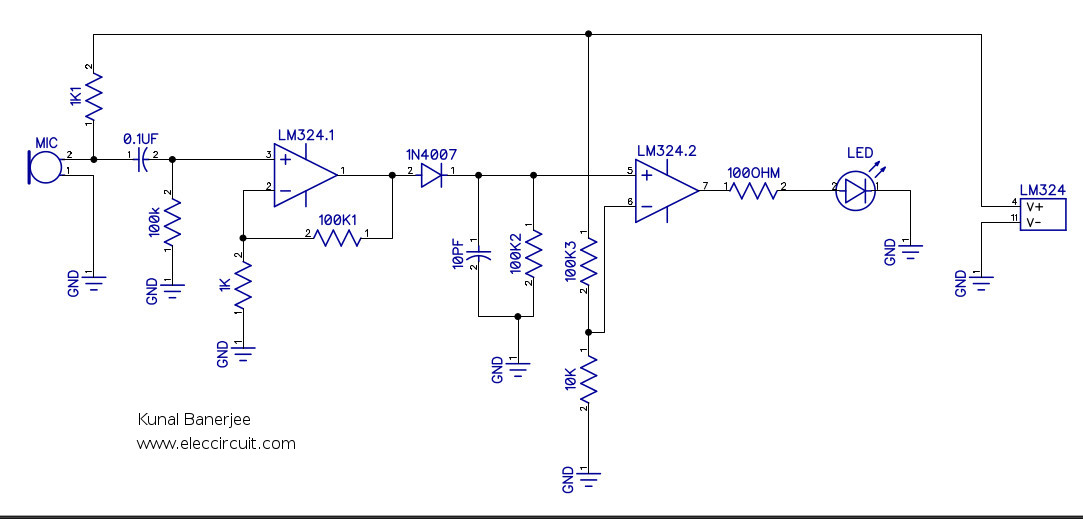
Figure 1 is the circuit diagram.
The circuit use Mic1 is a condenser microphone, when it gets the sound make the voltage across changing as AC signal and amplified by LM324 op-amp and show the sound with LED1 at the output.
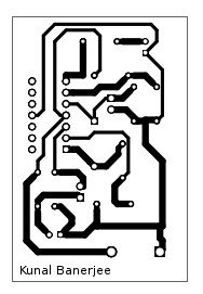
Figure 2 the PCB layout
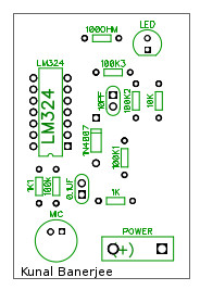
Figure 3 The component layout.
The single power supply voltage is 5V-12V.
Whistle activated light switch circuit with PCB
Surprisingly much, can turn on – shut down electric devices with a whistling sound.
This is simple sound control circuit as the Whistle activated light switch circuit, that different from a little common circuit is requires high-frequency noise Such as whistle sound etc.
The heart of working in this circuit is IC1 (UM3763) that is designed for this particular work. The figure below shows a circuit in actual use.
How circuit works
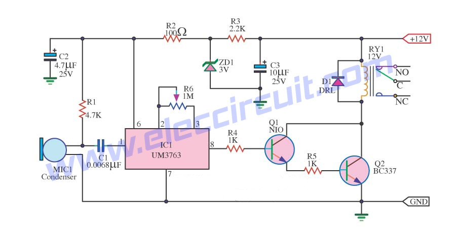
The IC1 needs to use a voltage only 3 volts. However, for convenience to using with a voltage relays up to 12V. I so use the R3 and the ZD1 is a reduced voltage for IC1 to only 3 V, as need.
We use R6 to adjust the frequency of the oscillator circuit internal IC1. In this case, sets the frequency at 18Khz. Input frequency using be in the range 1/10 – 1/15 of the frequencies in above. In the frequency between 1.8kHz to 1.2kHz.
The output of the circuit will change state each time to get an input signal comes. The output signal at pin 8 goes to the base of Q1 to drive the output of the transistor Q2, which acts as a relay to drive the pace of the sound input signal.
Parts detail
IC1: UM3763__Analog IC – Datasheet Reference
Q1: NIO is BC547, 45V 100mA NPN Transistor
Q2:bBC337 50V 800mA NPN Transistor
0.25W Resistors, tolerance: 5%
R1: 4.7K
R2: 100 ohms
R3: 2.2K
R4, R5: 1K
C1: 0.0068uF 63V Polyester Capacitor
C2: 4.7uF 16V Electrolytic Capacitors
C3: 10uF 16V Electrolytic Capacitors
D1: DRL is 1N4148 75V 150mA Diodes
ZD1: Zener Diode 3V 0.5W
Relay
Microphone condenser
B1: 9-volt battery Or 9V power supply circuit
Note:
The UM3763 is a CMOS LSI circuit which contains analog signal amplifiers and frequency detector for driving motor. It is designed for use in electronic devices and other similar applications. It is packaged with 8 pins DIP.
How to build this project
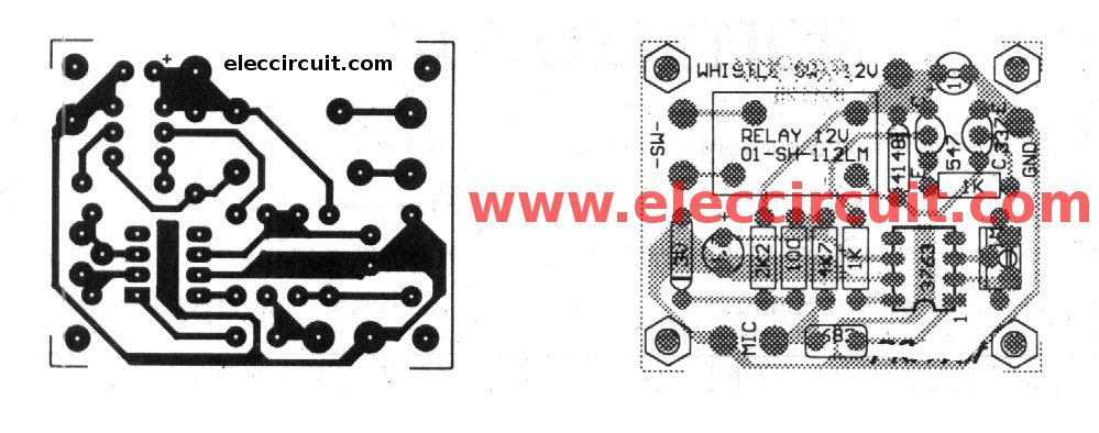
Figure 2 The PCB and components layout of this project
You put all devices electronic together onto the PCB as circuit diagram correctly complete. As figure 2 You may change the R6 to 1M preset for can adjust circuit in the sound frequency range as you wanted in Easily.
When the circuit finish. Then, check for error again. Next, bring the power to the circuit immediately.

Related Posts


I love electronic circuit. I will collect a lot circuit electronic for teach my son and are useful for everyone.
can the output drive a dc motor and if it is yes, how the motor driver will work from the 9v dc source?