The oscillator or the frequency generator, By most popular use NE555 or transistors or various gate. The output frequency setting depends on the resistance or capacitance As well as use the crystal control or frequency to the circuit. The frequency generator will see that has Designs commonly used in electronic circuits, specifically the digital circuit.
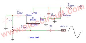
This is Simple VCO circuit using Schmitt trigger as Figure 1 is Voltage Controlled Oscillator (VCO) by using the 74HC14 IC, which inside the IC include up to 6 Schmitt trigger, but applied just only one can also be the frequency controller by voltage.
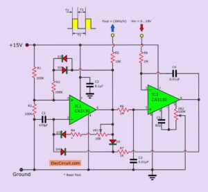
The pulse signal waveform in Figure 1, At point A, the input voltage start at 0 volts. The output of the inverter will be “high”, when has voltage signal come to input or use the voltage control-VC, or at place A has voltage rises.
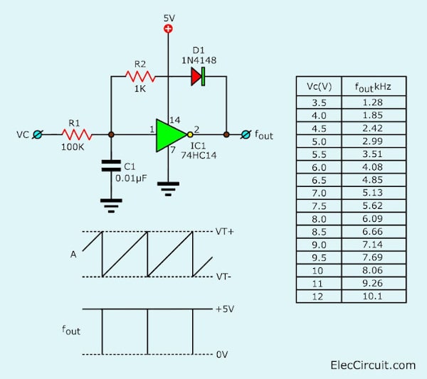
Figure 1 The VCO-using schmitt trigger
The capacitor-C1 will charge through a resistor-R1. But when the voltage rises until the maximum value to trigger to the inverter gate works or is voltage-VT+ output from the inverter will into as “low” and C1 will discharge through R2 and diode- D1 which is in brief range.
The resistor-R2 affects a frequency of control voltage-Vc, capacitor-C1, and Properties of the inverter will affect the width of pulse frequency to output. The correlation between the control voltage and output frequency, see in the table below. The power supply of the circuit is +5 volts, The voltage is controlled in a range of 3.5-12 volts, and the frequency output of 1.28kHz to 10.1 kHz.
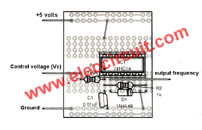
Figure 2 the components layout of the VCO using Schmitt trigger
How to build
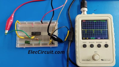
Although this project is an experiment. Normally we are always on the breadboard. But sometimes we make the actual use on the purpose PCB board as Figure 2 is the components layout of this project.
Which detail of building I do not describe because it has the same characteristics as before circuits. You will not be bored with it. But you shouldn’t negligence the project carefully.
The component list
Resistors, size ¼ W +5%
R1: 100K
R2: 1K
Capacitors
C1: 0.01uF 50V Polyester
Semiconductors
D1: 1N4148, 75V 150mA Diodes
IC1: 74HC14, Hex inverting Schmitt trigger
Other
a perforated board

Related Posts

I love electronics. I have been learning about them through creating simple electronic circuits or small projects. And now I am also having my children do the same. Nevertheless, I hope you found the experiences we shared on this site useful and fulfilling.
The circuit has two R1s. Which is R2?
Hello Mike,
Thanks a lot. I updated it.
Have a good day.