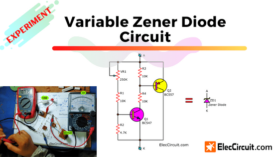
This is a Variable Zener diode circuit that we can use instead of a general Zener diode. We can adjust its voltage (VZ) and it consists of a small number of components that can easily be found at a local electronics store near you.
Often we use the Zener diode as a fixed reference voltage. Although, it will have a wide range of breakdown voltages (Vz) to choose from about 2V to 200V. But we can not adjust the voltage level of Vz. Because it has its own specific voltage. For example, if we use a 12V Zener diode. We cannot adjust the voltage down to 10.5V.
Thus, this Variable Zener diode circuit is a better way for us. The circuit represents a Zener diode where the voltage can be adjusted.
Read: What is Zener diode? Its principle working and example usage
Importantly it has more features than a normal Zener diode
- The Zener voltage (Vz) can be adjusted from 3V to 25V.
- Higher input impedance (20 to 50 ohms) rate under the maximum load.
- Temperature coefficient just only about -2 mV per degree celsius.
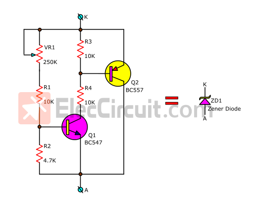
The Variable Zener diode circuit diagram
Variable Zener diode circuit working
Look at the circuit above. When the voltage at the base of Q1 exceeds 0.6 volts. The Q1 conducts the current, causing Q2 to conduct the current as well.
So, the voltage across the circuit does not increase, the same as how a normal Zener diode works.
This Zener Voltage(VZ) is determined by the ratio of (VR1+R1) and R2.
So, we adjust VR1 until getting our desired Zener voltage(VZ).
But when in real usage, you might replace VR1 with a normal resistor instead.
Due to the Q2 transistor can only endure the current of about 0.1A, thus this circuit is limited to the current of 100mA.
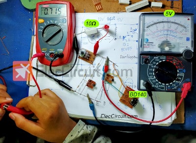
Experiment variable Zener diode circuit
My daughter assembles this circuit by soldering each and every component leads with copper wire. She doesn’t like using a breadboard.
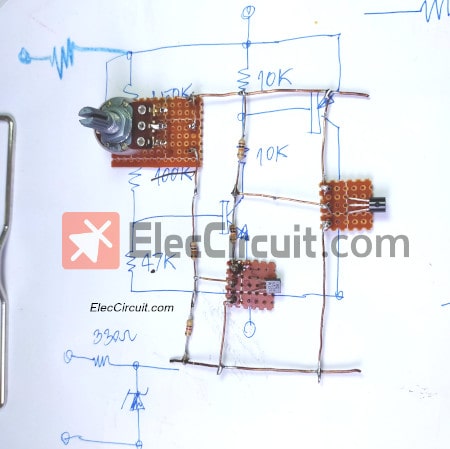
Though, the assembling process of the circuit is relatively slow. But it can help her better understand the working principle of the circuit.
This circuit works like a standard Zener diode, so it needs a resistor to reduce the current. We use a 330Ω 0.25W resistor for this.
For information on How to use Zener Diode
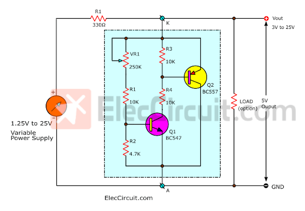
We use a 1.25V to 25V LM317 power supply as the input voltage and set VZ to 5V.
First, we will adjust the input voltage to 12V. Then, adjust VR1 until the output voltage is 5V (VZ). Next, increase the input voltage to 15V, 18V, and 25V and observe the change in the output voltage. After all of that, the output voltage still remains constant at 5V. So, it worked as well as a Zener Diode.
Paul anthony bridge said, “I suppose the buffer transistor BC557 can be a Darlington, or a PNP/NPN pair (Zlikai-pair) ?” It’s an interesting concept. Because we like to experiment with power supply circuits. With this idea, we might get a good shunt regulator.
Easiest way Good for my daughter is to add one more transistor to Q2 in Darlington pair.
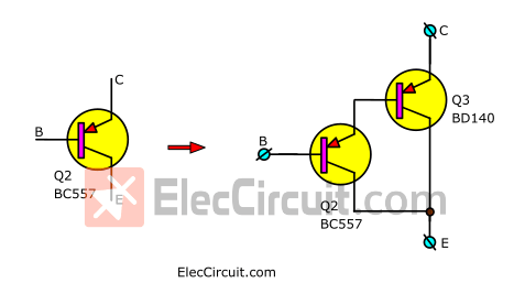
We add BD140 transistor as Darlington pair. It makes this circuit can endure the current about of 1.5A. Real experimentation, it’s a good way to learn. Will it be according to the theory or principle that we thought or not?
Read also: How to use 7805 voltage regulator
Parts you will need
Q1: BC547, NPN transistor 0.1A 40V
Q2: BC557, PNP transistor 0.1A 40V
Q3: BD140, PNP transistor 1.5A 100V
VR1: 250K Potentiometer
R1, R2, R3: 10K, 0.25W Resistor
R2: 4.7K, 0.25W Resistor
Keep reading: ‘Super Steady Zener diode voltage regulator’ »
Related Posts


I love electronics. I have been learning about them through creating simple electronic circuits or small projects. And now I am also having my children do the same. Nevertheless, I hope you found the experiences we shared on this site useful and fulfilling.
Can any one send me an Power on delay timer ( Delayed on ) on my id [email protected]. plz send this circuit..
Thanks In Advance
I suppose the buffer transistor bc557 can be a Darlington, or an pnp/npn pair (Zlikai-pair) ?
Hello Paul anthony bridge,
Currently, we are testing this circuit according to your curiosity. Please be patient.
Thanks.
Thank you for that !
It’s alright. I and my dad will work hard to learn more electronics. I hope it will be useful for you. 🙂
variable zener diode circuit is v good for many application.ilike tnank
Circuit use ful
many circuits send my mail
zener diode range –
input voltage-
range of resitance
i have new model ciruit design
Can use Q3 are MJ2955?
Yes, you can use MJ2955 or TIP2955, or TIP42.