This is a 0-30V 5A variable benchtop power supply circuit, with a voltage and current adjustable system. The output voltage 0-30V and a maximum current of 5A.
Use LM723 as a voltage regulator designed primarily for series regulator applications. By itself, it will supply output currents up to 150 mA. So need to use two transistors 2N3055 for boost up current to 5A.
There are two circuits to learn.
- DC Power supply 0-30v 5A, Adjustable regulator
- 0-30V 0-5A variable supply with current adjustable
DC Power supply 0-30v 5A, Adjustable regulator
This is DC Power supply 0 30v 5A, an Adjustable regulator is special that the output to 5A current. It uses LM723 DC voltage regulator IC + 2N3055 power transistor x2 to increase current up. So do the current too much than this circuit (easy circuit)
To use transformer 5A, Transistor 2N3055 to Hold Heatsink, VR1-5K to ADJ Volt Output.
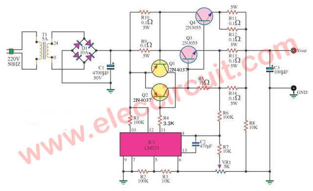
Circuit Diagram of Variable Regulator 0-30V 5A using LM723 and 2N3055 x 2
We do not offend you, In this Power supply circuit 0-30V 5A is adapted to the work
direct follow want of all of you.
This circuit is still the principle original everything. Just only changes the current limiting circuit. by use the resistors 0.1ohm 5W two pieces for the parallel, to be able to withstand loads as wanted.
We should not forget, use the resistor size 0.1Ω 5W amounting 2 pieces to parallel each other
Then, connected to the emitter of the two 2N3055. To offset features that might be slightly different, these two transistors.
Recommended: 7805 regulator datasheet & pinout
Parts you will need
IC1: LM723
Q1, Q2: 2N4037 or BD140 PNP transistor
Q3, Q4: 2N3055
BD1: Bridge 10A 400V
0.5W resistors
R1, R2, R6: 100K
R3, R7, R8: 10K
R9, R10, R11, R12, R13, R14: 0.1Ω 5W
VR1: 5K or 10K potentiometer
C1: 4,700uF 50V to 7,200uF 50V Electrolytic
C2: 470pF 50V Ceramic
C3: 100uF 50V Electrolytic
T1: Transformer 24V 5A
PCB, big heatsink, and more.
To create just operators device in a PCB form and then to make correct completed is available. Without you have adjusting customized at any the circuit.
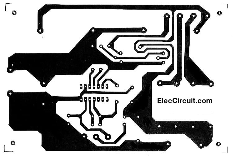
PCB layout
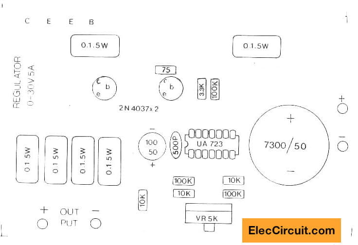
The Components layout of Regulator 0-30V 5A using LM723 2N3055
Note: This is so the old circuit.
It does not has a reference voltage for 723 and not fully overload protection. Please look at :
0-30V 0-5A variable supply with current adjustable
This circuit is better than the above circuit. Because use CA3140 for Control Current and Voltage output in easily. And full overload protection.
- P1-50K for control current
- R20-50K for Adjustable output voltage
- R19-5K for fine Adjustable voltage output
- Transformer—use 5-8A at 32V and 18V voltage. Read more below!
Note: This circuit is not suitable for the beginner. It is best for professional only.
How it works
In the 0-30V 5A regulator circuit below. It uses a precision voltage regulator system.
LM723 is the main part to control the output voltage precisely by itself.
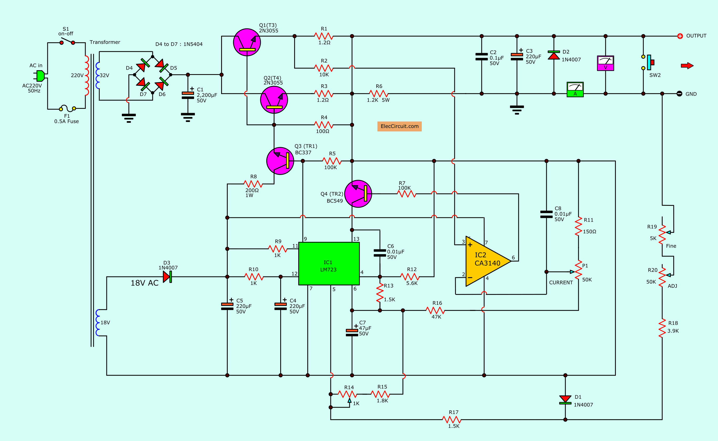
This circuit has 2 unregulated power supply, 43V, and 24V.
43V rectifier
It gets the AC voltage of 32V from transformer secondary. To rectify with a bridge rectifier, four 5A diodes.
They power a positive voltage to a collector of two power transistors, 2N3055. Both transistors are connected in parallel to increase the high current to the output load.
But in the beginning, 2N3055 does not conduct. Because they need to biased current from Q3-BC337 first.
So, we need to have another rectifier.
24V rectifier
This is a power supply for a control voltage regulator system. To begin with, we rectify the 18VAC from the transformer into 24V DC using a D3-diode and C5-filter capacitor.
Then, the 24VDC comes to resistor-1K to power to pin 12(V+) and pin 7 (V-) of LM723.
While the 24VAC also powers CA3140 op-amp IC at pin 7(V+) and pin4 (V-). This is a limiting current system of this circuit.
When the 24VDC flows through 1K resistor pin 11 (VCC) of IC1. It makes the transistor inside can supply voltage output of pin 9.
So, there is a voltage to bias the base of the Q3 transistor. It is working to conduct current from 24VDC through resistor 200Ω 1W to C-E of that transistor.
It results in both transistor 2N3055 get a biased current. So, they can power the current to the output.
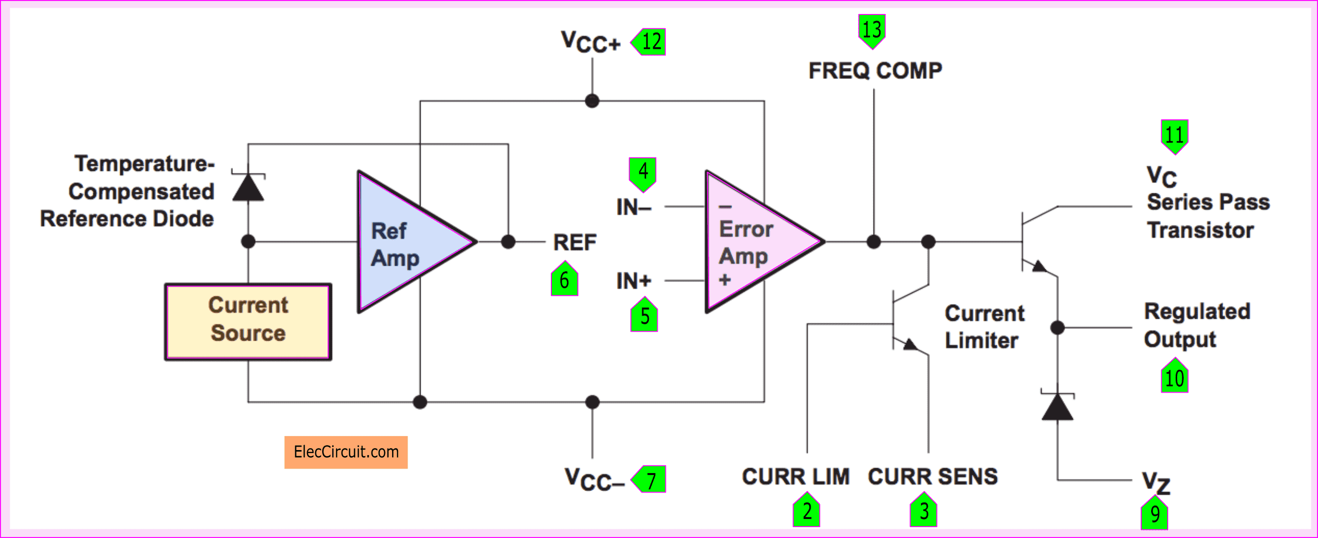
Block diagram inside LM723
Look at in the block diagram inside uA723. This voltage can be controlled by comparing the voltage pin 4 and pin 5.
Which both inputs of op-amp have 2 pins. Pin 5 is non-inverting and Pin 4 is inverting.
For pin 6 act as set the reference voltage.
If you want to change the output voltage. You change the voltage at pin 4 and pin 5.
In this circuit, we should choose to adjust the voltage at pin 5. Because it controls the voltage in a linear positive.
If the pin 5 voltage rises up. It makes the output pin 9 is positive up. Of course, there is a lot of biased currents.
Which we can rotate the potentiometer 50K to adjust the output voltage 0-30V in normal and 5K in fine adjusting.
Limited current
CA3140 is Bi MOSFET Operational Amplifier, it acts as limit the current in this circuit. If the current is more than 5A. This will cut off the regulator immediately—with stopping 2N3055 transistor working.
How it works?—We use a comparing voltage between pin 2 and pin 3. When the transistor Q1 works over current than normal. Then, pin 3 will compare the voltage with pin 2.
It makes the positive voltage out of pin 6 to bias the base of BC549. Then, BC549 pull the voltage at pin 13 of LM723 down and no output voltage. This circuit safe.
Note: Before Building it
I publish this circuit. Because of the benefits of medical. But I never tried it at all. So I can’t confirm that Is it works? I sincerely apologize. If you are looking for a 0-30 variable power supply.
I recommend
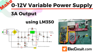
- 0-30V 3A Variable Power Supply circuit
- 0-50V 3A Variable power supply
- LM338 Adjustable Power Supply 5A and 10A
They are tested.
Also, You can increase current up to 5A by adding a transistor like this.
Okay, friends, You are smart! you want to try it for everyone.
I suggest you assemble the parts on a universal PCB. Then check all for errors after assembling them. I believe that the person who built this circuit has a good background in electronics. You can definitely create.
Parts you will needs
IC1: UA723
IC2: CA3140
Q1,Q2: 2N3055- 15V 60V transistor
Q3: BC337-0.8A 40V NPN transistor
Q4: BC549-0.4A 40V NPN transistor
0.5W 5% resistors Except special
R1, R3: 1.2Ω 5W
R4: 100Ω 5W
R6: 2.2K 5W
R5,R7: 100K
R9,R10: 1K
R8: 100Ω 1W
R9, R10.: 1K
R11: 150Ω 0.5W
R12: 5.6K
R18: 3.9K
R16: 47K
R13: 1.5K
Electrolytic Capacitors
C1: 2,200μF 50V
C3,C4,C5: 220μF 50V
C7: 47μF 50V

How it builds
First of all, we should get all the components on the lists below. Then, get the PCB. You can also use a perforated board. Look at the PCB layout and the components layout.
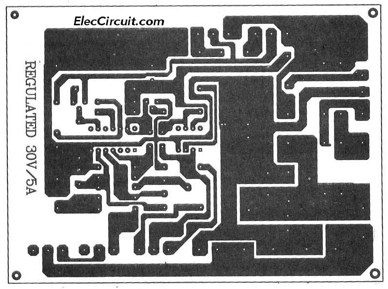
The PCB copper layout
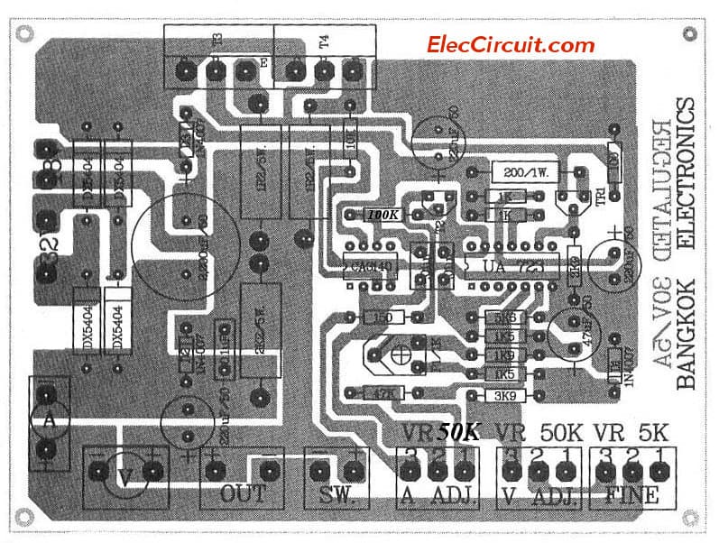
The component layout

Related Posts


I love electronics. I have been learning about them through creating simple electronic circuits or small projects. And now I am also having my children do the same. Nevertheless, I hope you found the experiences we shared on this site useful and fulfilling.
Dear electronic,
I wanted to build your own “Variable Regulator 0-30V 5A by LM723, CA3140, 2N3055” but there are inconsistencies between the PCB and the schema, namely:
1) R11 = 150 ohms connected to pin 4 or pin 6 of CA3140?
2) P1 (current) = 50k (scheme) or 5k (PCB)?
3) R7 = 100k (scheme) or 10k (PCB)?
4) pin 5 of the mass of uA723 18V with pin 7 (schema) or only R14 and R17 (PCB)?
5) R13 = 1.5 ohms (schema) or 1.5 k (PCB)?
Many thanks to those who answer me solve my doubts.
Thank you sincerely.
Hola amigo
siento una inquietud
que es un booster, y que función cumple, en cuanto al diagrama no es muy legible el transformador a utilizar, en el diagrama figura dos entradas u cuales son.
tienes un email donde pueda escribirte
saludos Daniel
Hi am a concern regarding this Variable Regulator 0-30V 5A by LM723, CA3140, 2N3055, transformer mention of:
32 volts as amperage
18 volt amperage as
SERIOUS C337 transistor (BC337) is correct as to what would be their equivalent C459
hugs greetings Daniel
Hey buddy hope not endure inconvenience but this source 50V, ie amplify 20 volts, so that the output gain 50Voltios, and that way you could modify greetings
hello . Thanks to those who respond to my
1) R11 = 150 ohms connected to pin 4 or pin 6 of CA3140?
2) P1 (current) = 50k (scheme) or 5k (PCB)?
3) R7 = 100k (scheme) or 10k (PCB)?
4) pin 5 of the mass of uA723 18V with pin 7 (schema) or only R14 and R17 (PCB)?
5) R13 = 1.5 ohms (schema) or 1.5 k (PCB)?
un booster es un reforzador de señales, ya sean señales de audio o radio frecuencia.
Thanks for the schema…
Yes, there are inconsistencies between the PCB and the schema.
firstly, i am not sure it works, till i tried to build from PCB (schema is just for the value reference)… the result is working properly as designed.
for other references:
32VAC input and 18VAC input MUST be supplied in different source (two secondary windings of single transformer OR use two transformers with 32VAC output and 18VAC output)….
why???….
please read the LM723 datasheet, the LM723 use 1.2V reference voltage, so the LM723 can not regulate the output if output below 1.2V!!!… the solution is “zero reference”, simply by crossing the 1.2V reference with negative of 1.2V… good luck.
HI
THANKS FOR YOUR GENEROSITY TO MAKE AVAILABLE THE DIFERENT ELEC. CIRCUIT DIAGRAMS
BEST REGARDS S.R.ROODASHTI
thanks to giving this circuit ,but some confusion in this circuit like as ,,
R13- 1.5 k or 1.5 om,input volt – ?,why s1 switch, c7 polarized or not,in4001 like as4007,Q4 c459 not find equiliant transister,how to connect R19and R20 can i shot point 1,2 and 3rd point to R20 plz clear my confusion .
thanks
arvind dhakre
7898948481
hi
this is better that answers of users asks write in this post for use all of friends
and
my question
R13 is 1.5 or 1.5k ?
tnx
Hello
is you built its power supply?
gostei da fonte de 0 a 30 volts, podeira me mandar o esquema completo, desde já agradeço .jean Pierre Houben brasil minas gerais
sir, i have built this circuit from pcb layout. but its not working properly. and i dont know why the switch is used for.??? please rply…early..!!??
One side of the 18V secondary winding feeds the positive output voltage, and could seriously damage your working model, nullifying your efforts and safety.
Dear friends
i think many wrong concepts in this design !
A – why used S1 ?
B- I sense resister will drop voltage near about 3volt when load is 5amp !
C- This is not a center voltage design . but schematic indicates different – ground & negative ! and where is output terminal ? and current meter connected how ?
and more please read carefully friends !
I faced same problem which already mentioned many users….can you plz update me …values of resisters ….
I faced same problem which already mentioned many users….can you plz update me …values of resisters ….
Hello I need info about the Variable Regulator 0-30V 5A by LM723, CA3140, 2N3055 circuit. What is the top transformer secondary voltage and power or amp rating.
What is the bottom secondary 18V secondary voltage and power or amp rating. Does Q3 C337 mean BC337? I do not have any ideas what Q4 C459 transistor is. It may be an extremely old transistor that needs an equivalent of a new transistor. Can you please answer these questions. Thank you
Bhai pcb layout to do is ka ap ki maharbani ho gi
This circuit not good..
Dear sir
I request you.
please you send Generator AVR complete circuit diagram.
montei a fonte de 0a30v e 0a5a funciona muito bem
Hello, Sergio
Thanks for your visit. How are you?
I’m glad you liked this circuit. And it is useful for you
Have a good day.
Apichet
This circuit is faulty. One side of the transformer’s 18V winding is connected to the positive voltage output, and could have disastrous results when initially powered up.
Hello
Thanks for your visit to my site. You are a good electronic man.
I am sorry to hear that it does not work.
However, I have always believed that learning from mistakes is the best of learning, it is always one step toward success. I noticed from your message. You are a great experimenter. You will surely succeed, I believe you.
Have a good day.
I didnt connected pin 7 of ca3140 to positive volts. Will this circuit will able to boot mobile and laptop. As i made a circuit using LM317, bd139 and 2n3055 which not booting mobile and I am anxious to make a circuit which can on latesh mobile handset and laptop. Pls help me resolve my issue as i dont have money to buy DC supply machine.
Bonjour à tous, je vous écris depuis la France. Je constate que plus aucun de vous ne s’est intéressé à cette alimentation depuis le dernier message d’Apichet Garaïpoom en date du 30 décembre 2021. Dommage qu’aucun des bricoleurs en électronique n’ait persisté pour faire fonctionner ce montage. Quoiqu’il en soit, je m’y suis lancé sans avoir vu aucun des messages ayant suivi cette parution. Effectivement il y a quelques erreurs entre le schéma et le montage sur le PCB.
J’ai réussi -non sans mal – à faire fonctionner ce montage en ne lui demandant pour l’instant que 4A sous 35 V environ; sauf que pour y parvenir j’ai dû remplacer Q3 (TR1) indiqué sur le schéma comme un BC 337, bien trop faible pour alimenter les 2x 2N3055, par un BD 679 -darlington- en boîtier TO126; et là, miracle l’alimentation a enfin répondu!
Autres différences entre schéma et PCB :
R5 indiquée comme 100K sur le schéma, n’en fait plus que 3,9 sur le PCB
C8 relié au moins de l’alimentation du 723 et du 3140 sur le schéma est relié à 6 du 3140 et à R7 sur le PCB
Autre chose: d’après mes connaissances la valeur de C1 est bien trop faible pour demander 5A à cette alimentation, sachant que la norme minimale -sauf erreur de ma part – est de 1000uF par ampère. Donc avec 2200uF on ne pourrait tirer raisonnablement que 2 A environ. Pour obtenir 5A il faut que C1 fasse au moins
10 000uF
Je n’arrive pas à faire fonctionner le réglage d’intensité avec P1 (donné pour 50 K) sur le schéma et sur le PCB, seule l’action de R14(1K) engendre une action lorsqu’on le ramène au minimum: le courant est coupé à la sortie. Je manque de connaissances pour savoir pourquoi ça ne fonctionne pas comme je l’imagine, à savoir qu’en réglant P1 à n’importe quelle valeur , la sortie devrait se couper lorsque la consommation en sortie dépasse cette valeur. Le remplacement de R7 de 100K à 3,9K n’a rien changé. Si l’un d’entre vous à la solution, je suis preneur!
Dommage que ce montage n’ait pas de “père”, on aurait pu s’adresser directement à lui.
Cordialement. Jacky
in english:
Hello everyone, I’m writing from France. I notice that none of you have been interested in this diet since the last message from Apichet Garaïpoom on December 30, 2021. Too bad that none of the electronic handymen persisted to make this assembly work. In any case, I launched myself without having seen any of the messages that followed this publication. Indeed there are some errors between the drawing and the mounting on the PCB.
I managed -not without difficulty – to make this assembly work by asking for the moment only 4A under about 35 V; except that to achieve this I had to replace Q3 (TR1) indicated on the diagram as a BC 337, much too weak to power the 2x 2N3055, by a BD 679 -darlington- in TO126 housing; and then, miracle the power supply finally responded!
Other differences between scheme and PCB:
R5 indicated as 100K on the schematic, now only 3.9 on the PCB
C8 connected to at least 723 and 3140 power on the drawing is connected to 6 of 3140 and R7 on the PCB
Another thing: according to my knowledge the value of C1 is much too low to ask 5A to this power supply, knowing that the minimum standard -unless I am mistaken – is 1000uF per amp. So with 2200uF we could draw reasonably only about 2 A. To obtain 5A it is necessary that C1 does at least 10,000uF
I can not operate the current setting with P1 (given for 50 K) on the diagram and on the PCB, only the action of R14(1K) causes an action when it is reduced to the minimum: the current is cut at the output. I lack the knowledge to know why it does not work as I imagine, namely that by setting P1 to any value, the output should cut off when the output consumption exceeds this value. The replacement of R7 from 100K to 3.9K did not change anything. If any of you to the solution, I’m ready!
Too bad this setup doesn’t have a “father”, we could have gone straight to him.
Sincerely Jacky
translation via Reverso
Bonjour à tous, bonne nouvelle j’ai trouvé la solution pour faire varier l’intensité: j’ai remplacé le transistor Q4 (TR2) donné pour un BC549 par un autre darlington, d’abord un BC517 (Hfe>40 000!) ce qui m’a permis de constater l’efficacité du potentiomètre P1.
Avec un transformateur délivrant30,5V à vide soit 43V cc redressé/filtré, j’ai pu alimenter une très grosse résistance sous 31,5V et 3,6A ce qui fait une puissance supérieure à 110W.
Par la suite j’ai changé de transformateur passant à un modèle délivrant un peu plus de 60V à vide ce qui redressé/filtré donnait 41,8V (sans charge). J’ai remplacé Q4 par un autre darlington, un BD681 en boîtier TO126. Alimentant à nouveau la grosse résistance, j’ai pu lui fournir au maximum 3,97A sous 34,8V en sortie d’alimentation, la puissance dépassant alors légèrement les 138W.
Je n’ai pu faire varier la tension en utilisant les potentiomètres P2/P3, ceux-ci n’étant d’aucune efficacité. Seul le potentiomètre P1 était efficace, faisant varier l’intensité et la tension à la fois, ce qui fait qu’on ne peut avoir de petite tension avec une grosse intensité et inversement, U et I étant indissociable, du moins pour cette alimentation.
Dans les jours à venir, je vais voir si je peux augmenter la puissance de sortie en trouvant un transformateur plus puissant.
Cordialement.
Jacky Thiellin
in English
Hello everyone, good news I found the solution to vary the intensity: I replaced the transistor Q4 (TR2) given for a BC549 by another darlington, first a BC517 (Hfe>40 000!) which allowed me to see the effectiveness of the potentiometer P1.
With a transformer delivering 30.5V vacuum or 43V dc straightened/filtered, I was able to supply a very big resistance under 31.5V and 3.6A which makes a power greater than 110W.
Then I changed the transformer to a model delivering a little more than 60V vacuum which straightened/filtered gave 41.8V (without load). I replaced Q4 with another darlington, a BD681 in TO126 housing. Feeding the big resistance again, I was able to supply it with a maximum of 3.97A under 34.8V power output, the power then slightly exceeding the 138W.
I was unable to vary the voltage using the P2/P3 potentiometers as they were not effective. Only the potentiometer P1 was effective, varying the intensity and the voltage at the same time, so that one cannot have small voltage with a large intensity and conversely, U and I being inseparable, at least for this power supply.
In the coming days, I will see if I can increase the output power by finding a more powerful transformer.
Cordially.
Jacky Thiellin