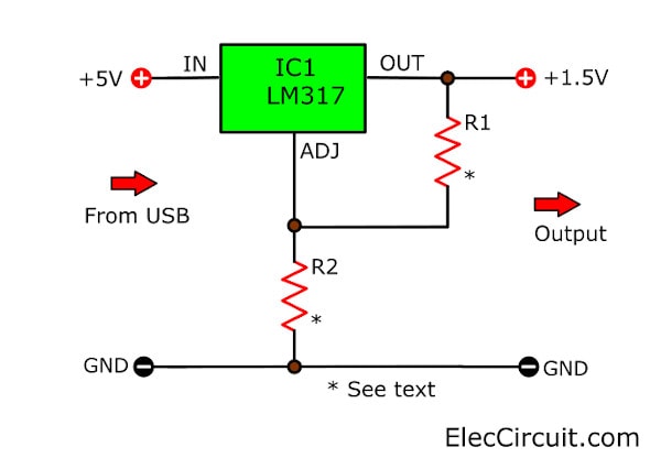
This is a USB 5V to 1.5V/3V Step-Down Converter Circuit. It is used instead of a normal AA battery.
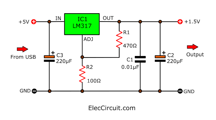
In the circuit, we use LM317 DC voltage Regulator. To reduce the 5V input voltage from USB Port to the 1.5V at 1.5A maximum output.
Even 3V output, this circuit can run well. Read below.
So, this circuit is simple, easy to builds and cheap.
How 5V to 1.5V converter circuit works
When we use a Cheap MP3 Player (or all Small Appliances). Which uses only one 1.5V AA battery as its power supply.
Are you a beginner? Learn Basic Electronics
Using the battery is very wasteful.
If we take it to listen to music in the house. Or when the AA battery is suddenly low power. We cannot find another one.
But we have a USB port. It is a popular port anywhere have this.
So…
We can use this circuit to convert 5VDC to 1.5VDC. The power adapter is USB Battery Replacement. To convert USB ports 5V voltage down to 1.5V.
Look at a circuit.
I used a popular IC – LM317. They use only 3 parts, include R1 = 470 ohms, R2 = 100 ohms, and LM317-IC1 so very easy.
From the LM317 Regulators CALCULATOR ,
We can calculate output voltage:
Vout = Vref x {1+ (R2/R1)
- Vref = 1.25 Volts
- Typically R1 is 220 ohms or 240 ohms as a datasheet,
But now this is 470Ω. - The R2-resistors is 100Ω
Then we test it in the formula above:
Vout = 1.25 x {1+(100/470)}
= 1.52V (about 1.5 volts)
Or you can change two resistors below
| Vout | R1 | R2 |
| 1.47V | 470Ω | 82Ω |
| 1.47V | 390Ω | 68Ω |
| 1.51V | 330Ω | 68Ω |
| 1.51V | 390Ω | 82Ω |
| 1.52V | 470Ω | 100Ω |
| 1.53V | 390Ω | 82Ω |
| 1.56V | 330Ω | 82Ω |
| 1.57V | 270Ω | 68Ω |
Learn: Resistor color code and how it works
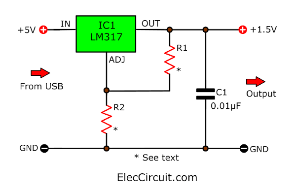
Low noise filter
In real usage, you may add 0.01uF 50V ceramic across the output to reduce any transients or noise.
How to build
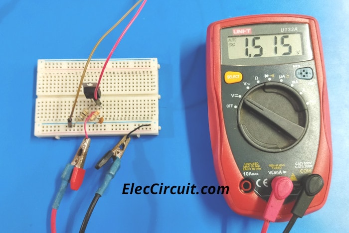
This cirucit is easy. You may not need use PCB. We can connect it directly. If your load use low current. You don’t need a heatsink. See below.
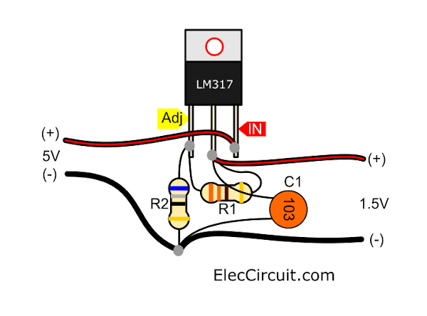
Also, you can test this circuit on the breadboad. See below. I measure the output voltage is 1.5V. It is good circuit.
Related Circuits
We hope that friends will enjoy listening to music on this circuit.
5V to 3V Converter circuit
Not only that, If you want to use 3V output or even 2.4V to replace two 1.2V batteries.. Can we do it?
Here is a 5V to 3V Converter circuit using LM317.

We can change R1 and R2 to set circuit. See in the table below.
| Vout | R1 | R2 |
| 2.36V | 270Ω | 240Ω |
| 2.4V | 240Ω | 220Ω |
| 2.5V | 470Ω | 470Ω |
| 2.96V | 270Ω | 390Ω |
| 2.97V | 240Ω | 330Ω |
| 3.03V | 330Ω | 470Ω |
| 3.05V | 390Ω | 560Ω |
| 3.06V | 270Ω | 390Ω |
| 3.06V | 470Ω | 680Ω |
| 3.08V | 150Ω | 220Ω |
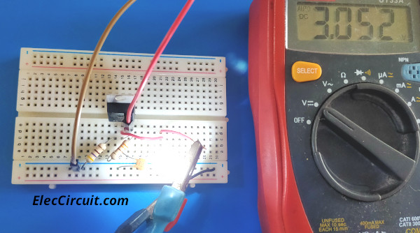
Then I test it with a white LED. It glows up. Next measure a voltage across it is 3.0V. This circuit worked.
Improved circuit
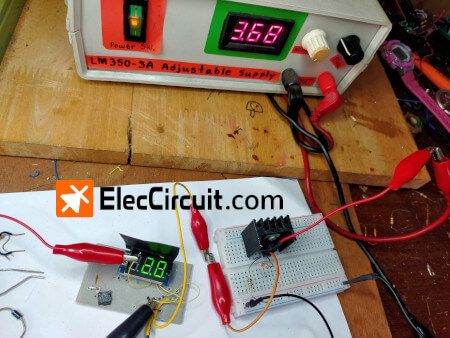
Sometimes, Loads consume a high current like 100mA. Makes the output is low voltage, 0.7V to 0.9V, and more ripple too.
We can reduce this problem by adding the electrolytic capacitors C2, and C3 at the input and output.
Look at the circuit below.
I use the 220µF 16V electrolytic capacitors. Or you can try 470µF or 100µF, the result is similar.
This circuit works well, and has a few devices, so it’s very easy to build and very cheap. But it’s a disadvantage! It seems it is not effective at all, up to 50% of power is wasted as heat. MrCal said correctly.
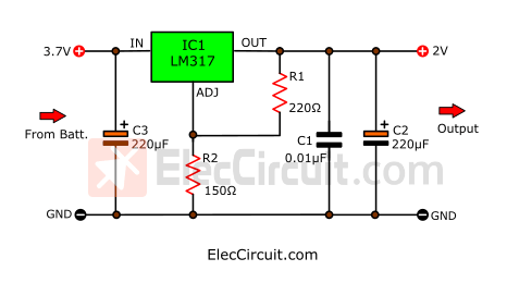
3.7V to 2V DC to DC converter
I try to use a 3.7V battery as input. It makes the output voltage 2 volts.
As circuit below, We use R1 = 220Ω and R2 = 150Ω.
What should we do? Use MC34063 Step-down Switching regulator circuit
and How to increase more current for 34063 chip 5V 2A buck converter
However, I love LM317. It is so useful. Learn more:
If you made it completely please share it with us.

Related Posts

I love electronics. I have been learning about them through creating simple electronic circuits or small projects. And now I am also having my children do the same. Nevertheless, I hope you found the experiences we shared on this site useful and fulfilling.
I got this website from my pal who shared with me on the topic of this
website and now this time I am browsing this web page and reading very informative
content here.
Hi there, I tried this step down set up, and I arrived at 1.0 volts. Where was the .5 volt lost?
This is great but what do I need to make usb to 3 volt step down?
Hello G,
Thanks for your question.
Yes, you can use it, 3V step down output by changing R1 and R2.
is this circuit work to power up my wall clock usually use a battery AA which is DC 1.5V ?
Hello yusof125,
Yes, It works with a wall clock that uses an AA battery, 1.5V.
Nice tried and worked
Hello DUBE,
Thanks for your feedback.
It helped to me very much, Thank you for your good site 💖🌹💖
Hello Alireza,
Thanks for your feedback.
HELP please, I’m trying to make this but since the loss of radio shack and maplins (places to ask questions) I’m getting totally lost as the places to buy components online are giving me way to many options. Its the resistors that are getting me confused, when I search for 220 and 100 ohms its asking me resistor type/ watt/… what am I looking for? thanks.
Hello David p mison,
Thanks for your visit. I am happy you like this circuit.
What is output voltage rates?
R1 = 220 ohms and R2 = 100 ohms right?
In normal we can use 0.5 watts resistor.
If the input voltage is 5V.
Thanks again
Apichet
Thank you for this post. It is really helpful. I know this IC can be regulated to 0volt on regulared PSU’s.
There’s a way may someone tell me how to lower at 500mV?
I really need 500mV for an Ohm meter based on arduino I working on.
I wish I could have studied electronics instead of computers sciences.
Hello Edcali,
You’re welcome. The datasheet said the entry-level is 1.25V. If the output is 0.5V. We may modify the circuit, I suggest in the next opportunity.
How effective is this LM317 in this application setup?
Hello MRCal,
Thank you for your visit to my site.
LM317 is a linear regulator IC. While it works, it will be hot.
It has low efficiency. But it’s cheap and very easy to use.
What do you think can be used instead of it?
If using a switching IC. It will be more efficient.
For LM317, I will try to find another way, to increase its efficiency.
….it seems it not effective at all, up-to 50% of power is wasted as heat.
Yes, you are correct. If your load is low current. It does not heat too much.
can i use this circuit to charge a 800mah nimh battery?
Yes, you can. But if you charge it directly.
The current of this power supply can be as high as about 1A.
Makes the battery too hot and charging time about 50 minutes. This way is not good for your battery.
You should have the optimal charging current is 0.1C or 80mA for about 10-12 hours. This way, it can extend the life of this battery for a long time. It’s very cost-effective from my experience. It can be recharged about 300 times or more.
You may this: https://www.eleccircuit.com/nicad-battery-charger-by-ic-lm317t/
Or https://www.eleccircuit.com/constant-current-circuits-transistors/
They charge with a constant current. It is good for this battery type.
Does anyone know how to change 3.7v to <1v? What resistor value do I need?
Thanks
It looks great!!! Can I get 1.5 V x 1.5 Amp. from this circuit?
“Hello,” my dear friend,
Yes, you can try it. But It may not be to 1.5A output. You may use LM350T, and use input current min 2A.
Have a good day.
Apichet
how can i get 2.4 volt out put
For 2.4V output set R1=240Ω, R2=220Ω
Good day,
I need 3.7 volt To 2 volt witch resistance i use for R1 and R2
Yesterday I and my dad tried connecting a circuit to reduce the voltage from 3.7V to 2V.
It works. See here: https://www.eleccircuit.com/usb-battery-replacement-by-lm317/#37V_to_2V_DC_to_DC_converter
🙂